Flexible joining / Handheld laser

Handheld Laser Welders

Product Overview

Handheld laser welding gives a metalworking team direct control of the welding path while concentrating energy at the joint. It is a useful route for varied sheet-metal assemblies, visible corners and accessible seams where fixture complexity would outweigh the benefit of automated motion.

CHENDA handheld laser welders address the joining stage between formed components and finished assemblies. For a stainless enclosure, the priority may be a corner that needs limited surface correction. For a small frame, it may be moving comfortably between different seam orientations. Head access, wire delivery and working position determine how effectively the operator can use the chosen laser configuration throughout a shift.

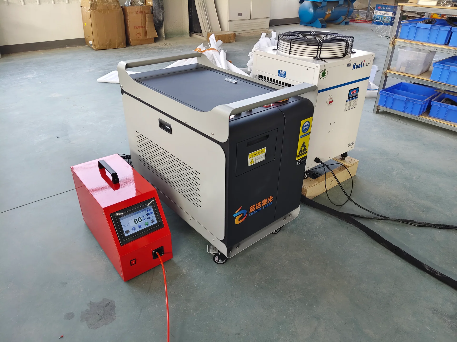
CHENDA handheld laser welding cabinet with a red wire feeder and a Hanli cooling unit.
Laser welder, wire feeder and cooling unit

Materials & Capabilities

Steel, stainless steel and selected aluminum alloys are candidates for application testing. Tell us the grade and surface condition: bare sheet, mill scale, galvanized coating, oil or protective film can require different preparation.

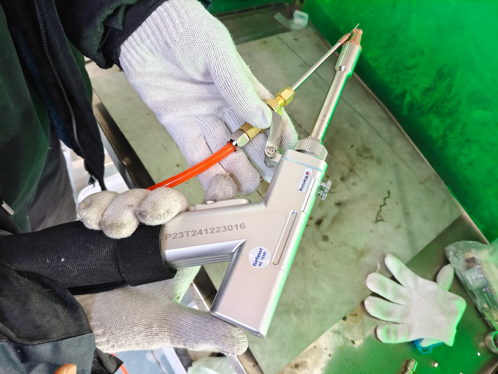
Handheld laser welding head showing the nozzle, wire guide and attached cable assembly.
Nozzle and wire access at the joint
Joint type Practical opportunity What to establish
Outside corner Joining formed panels with an accessible visible edge Edge alignment, bead shape and cooled corner geometry
Butt joint Joining coplanar sheet edges Gap, edge mismatch and penetration target
Lap joint Joining overlapping components Beam position, overlap and required fused interface
T-joint or fillet Joining a flange, bracket or frame member Head angle, access and required weld section

The thickness of either component is only one input. An unequal-thickness joint can direct heat differently from two matching sheets. An inaccessible root or a required seal can also change the welding approach.

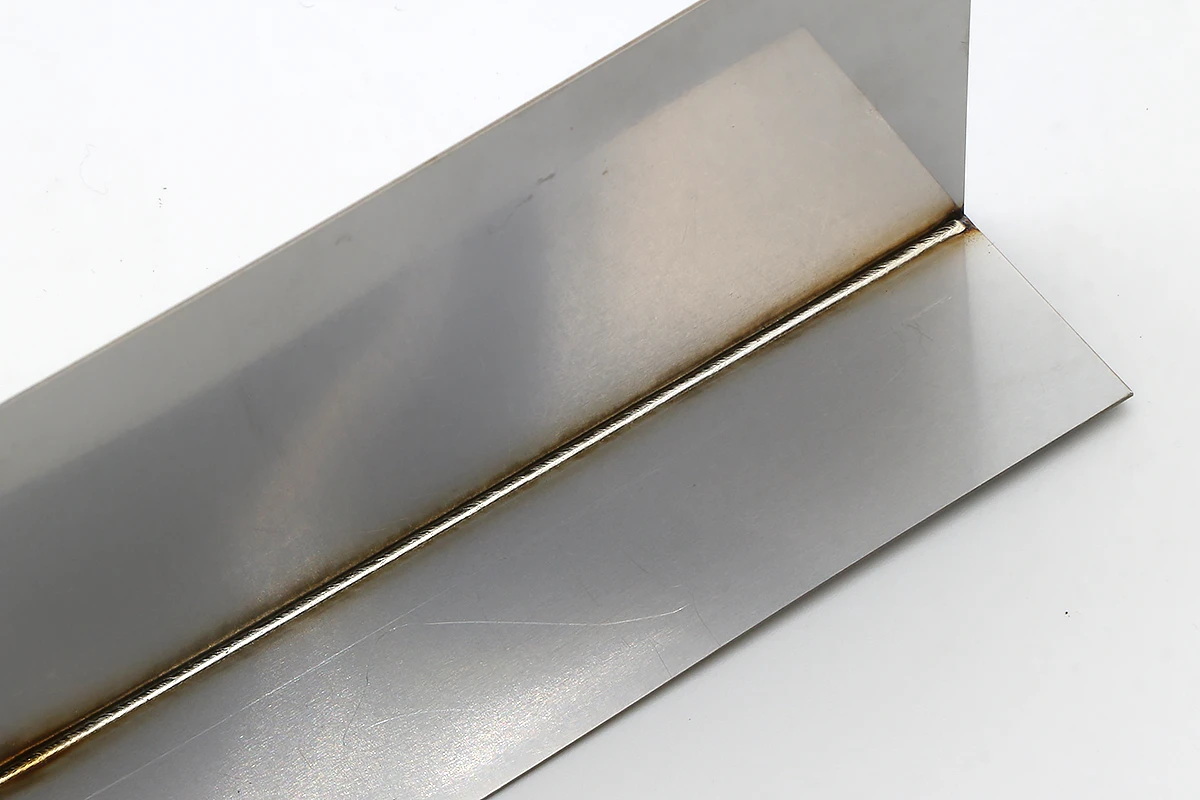
Third-party laser-welded sheet-metal inside-corner sample with a continuous visible weld seam
Close-fitting sheet corner · laser-welded sample · smartDIYs

Thin corners and wider gaps behave differently

A close-fitting outside corner may allow the two edges to melt together with little additional material. If the edges pull apart along the seam, the same settings can leave an inconsistent section or an opening. More laser output does not replace the metal missing from the joint. Better fit-up, an appropriate joint design or a validated filler-wire process addresses a different problem from insufficient energy.

For a lap joint, the visible bead sits above the mating interface. The application must establish how the lower component participates in the weld. This is why a sample should reproduce the actual overlap and component thicknesses rather than use a convenient flat strip.
Features & Engineering

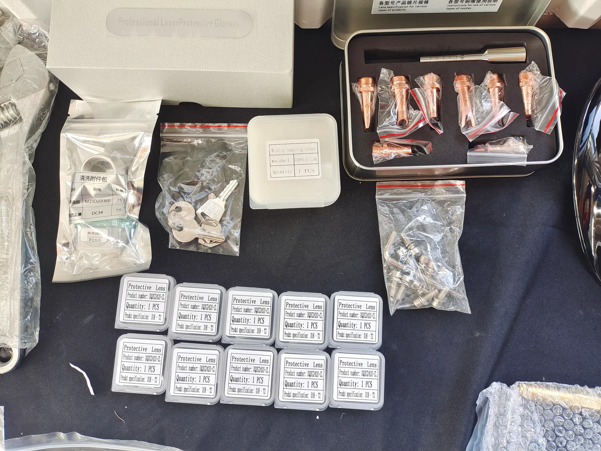
Copper welding nozzles, packaged protective optics and accessories arranged on a work surface.
Joint-specific consumables
Handheld laser welding head showing the nozzle, wire guide and attached cable assembly.
Head, nozzle and wire guide
Copper welding nozzles, packaged protective optics and accessories arranged on a work surface.
Nozzles and protective optics

A usable head position creates a steadier seam

Nozzle shape, wire entry and cable routing should allow the operator to maintain the selected travel angle without twisting the wrist or dragging the delivery cable across the work. Check inside corners and the ends of long seams before choosing the head arrangement. A head that reaches the start of a seam may become awkward when the operator moves around a corner or the cable meets a fixture leg. Supporting the work at a sensible height helps maintain a steady path without relying on hand strength alone.

Beam movement and travel speed work together

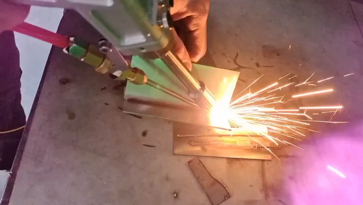
Handheld laser head joining a sheet-metal sample
Travel path and beam position work together

Where the selected head supports beam oscillation, its pattern and width distribute energy across the joint. A wider sweep spreads the available output over a wider region; at otherwise unchanged conditions, it should not be assumed to preserve the same local energy concentration or penetration. Its value is in matching the energy distribution to the intended bead and joint.

The hand supplies a second movement: travel along the seam. A slow finish, a hesitation near a clamp or a sudden change in wrist angle alters the local process. Stable support and a comfortable movement path help avoid overheating at the end of a seam while retaining sufficient joining through the middle.

Wire supports a defined joint objective

Filler wire can help produce reinforcement or address a validated fit-up condition. Stable delivery requires the correct wire, guide, drive arrangement and alignment with the weld pool. Wire addition is a process choice, not a repair for uncontrolled cutting and bending variation.

If too much wire enters for the available melting conditions, it can disturb the process or leave excessive buildup. If delivery is intermittent, the bead can vary even when the operator’s hand is steady. A wire change therefore involves its alloy, diameter and feeding path—not only selecting a different diameter on a screen. Keep the wire approach visible and unobstructed through the tightest part of the joint.

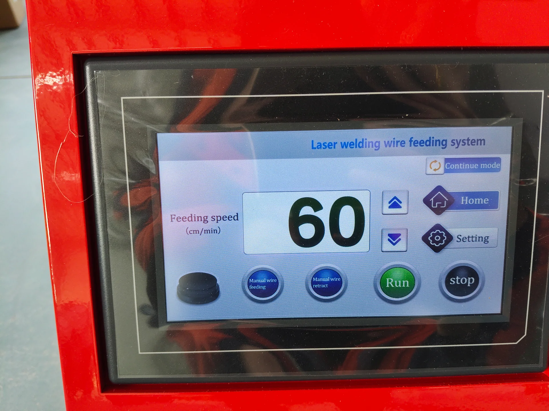
Touchscreen on a red laser welding wire feeder showing feeding controls.
Wire-feed speed and delivery controls
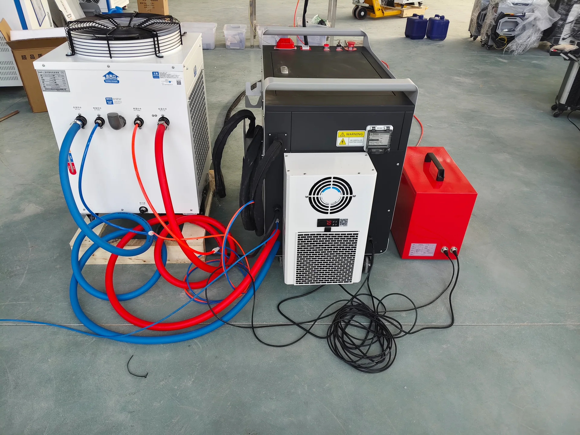
Rear view of a laser welding cabinet and chiller with connected cooling hoses and cables.
Cooling connections

Cooling belongs in the production decision

Compare the proposed cooling arrangement against ambient temperature, working hours and available services. Water-cooled and other cooling configurations have different maintenance needs; neither should be selected by cabinet size alone.

Technical Specifications

Request the configuration sheet for the proposed unit. The following fields connect its ratings with your actual welding task.

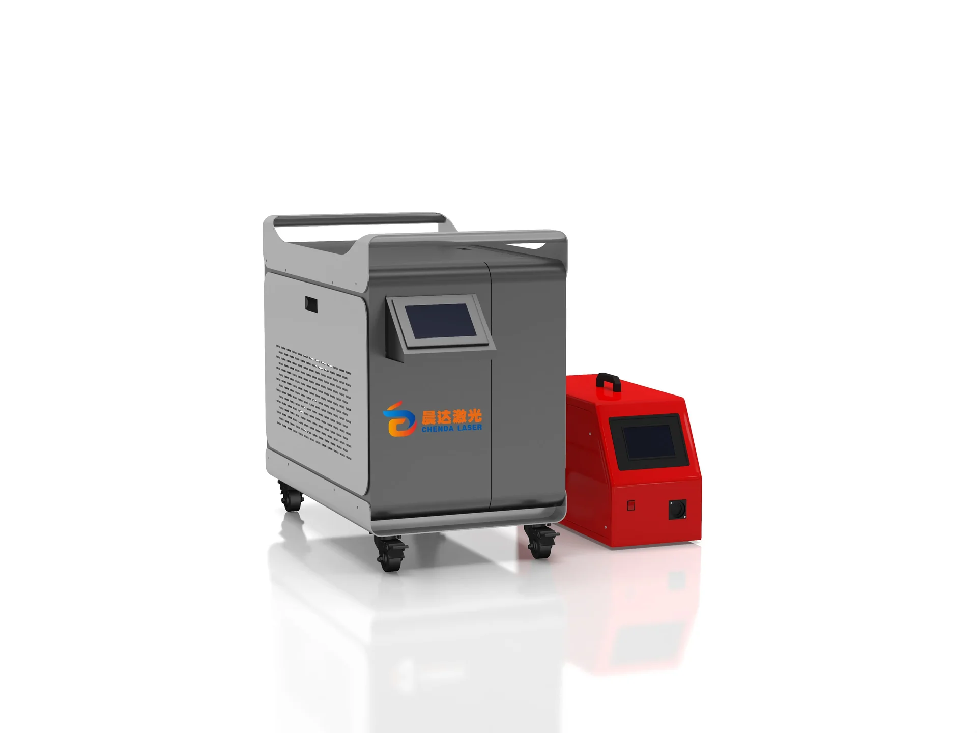
Compact gray CHENDA laser welding cabinet with an external red wire feeder.
Parameter Unit or description Selection basis
Rated laser output W Material, joint geometry, desired penetration and travel speed
Qualified material range Grade and thickness in mm Results from the specified joint and preparation
Head movement settings Pattern; width in mm where supported Bead width, energy distribution and nozzle access
Filler wire Alloy and diameter in mm Compatibility, reinforcement and feeder/head limits
Wire-feed range m/min Stable delivery at the approved welding speed
Delivery cable Usable length in m Work-area layout, bend limits and cable protection
Cooling Type; required fluid or air conditions Duty and site temperature
Electrical supply V, phase, Hz and total input kW Complete machine demand, including auxiliaries
Shielding gas Type; operating flow in L/min Material, nozzle and approved procedure

No single maximum-thickness figure describes every handheld weld. Separate the required joint penetration from the parent-sheet thickness, and evaluate the result at a practical operator travel speed.

Samples & Demonstration

For a cabinet project, send a formed corner as well as flat coupons. For a tube assembly, include the smallest clearance around the joint. These samples reveal whether the nozzle and wire can reach the seam without damaging the visible surface.

A useful trial compares the seam face, underside where accessible and cooled dimensions. Include normal production fit-up. If strength or sealing matters, agree on an appropriate inspection method; a smooth bead alone cannot demonstrate either.

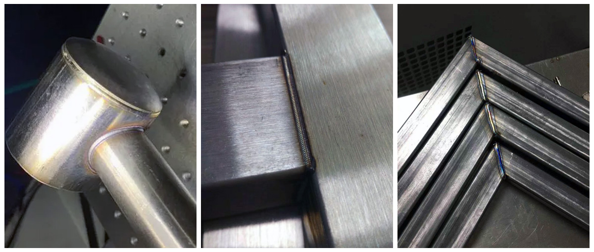
Third-party handheld-laser-welding samples showing a round-tube connection, a rectangular joint and welded mitered tube-frame corners
Different tube-joint geometries · laser-welded samples · Suntop Laser

What the sample can reveal

Third-party laser-welded sheet-metal inside-corner sample with a continuous visible weld seam
Visible weld condition · smartDIYs
Sample observation What it helps investigate Why it matters in production
The bead changes near the end of a long seam Hand speed, support and access Repeated finishing at one location may come from the working posture
One edge melts back more than the other Alignment, edge geometry and unequal heat flow A balanced-looking setup may still heat the components differently
Wire-fed bead height varies Wire approach, delivery and travel consistency Surface buildup can create avoidable grinding or fit interference
A corner moves after cooling Fit-up, restraint and seam sequence A good hot appearance may not preserve the final enclosure shape

Use these observations to narrow the investigation. Surface appearance cannot by itself identify an internal pore, establish penetration or prove that a sealed assembly is leak-free.

Configuration & Options

Discuss the matched laser source, welding head, controller, cooling and wire-feed arrangement as one package. Nozzle sets and consumables should follow the selected joint types. Confirm which items are supplied with the machine and which are separately quoted.

Additional process modes may be available on a proposed configuration, but welding, surface cleaning and cutting have different head requirements and operating controls. Select each intended function explicitly. A multifunction description does not establish that every mode uses the same setup or achieves the same result on every material.

For welding itself, prioritize options that remove a daily constraint: a suitable corner nozzle for restricted access, a compatible feeder for the chosen filler, or a cooling arrangement appropriate to sustained use. Extra patterns or accessories create little value if the operator cannot maintain the intended head position on the actual assembly.

Copper welding nozzles, packaged protective optics and accessories arranged on a work surface.
Process-compatible consumables
Touchscreen on a red laser welding wire feeder showing feeding controls.
Filler-wire delivery
Painted metal filing cabinets with open drawers
Cabinet application · visual reference

Applications & Workflow

Handheld welding is particularly worth evaluating when a workshop moves between cabinet corners, small frames, brackets and other accessible fabrications. Prepare the edges, locate and clamp the parts, set the approved program and weld in a sequence that protects the final geometry.

Allow for tacking, repositioning and inspection when estimating output. For long visible seams, consistent operator posture and workpiece support can be as valuable as a faster nominal travel speed. If the same path repeats frequently, compare an automatic platform or robot before expanding manual capacity.

A cabinet workshop can organize a handheld station around formed corners: locate the panels, retain access to the visible edge, join in the planned sequence and inspect after release. A furniture shop may instead need supports that let the operator rotate a small frame without straining the head cable. These arrangements preserve flexibility while reducing the handling variation that makes one acceptable sample difficult to repeat.

Installation & Support

Plan a laser-controlled work area with appropriate beam containment, access control, reflection assessment, extraction and protective equipment. A conventional arc-welding curtain or helmet should not be assumed suitable for the laser wavelength and exposure conditions. Training needs to cover the complete work area as well as machine operation.

Routine care includes checking nozzle condition, wire delivery, protective optics and the specified cooling system. Protect the fiber cable from sharp bends, impact and contamination during movement and storage.

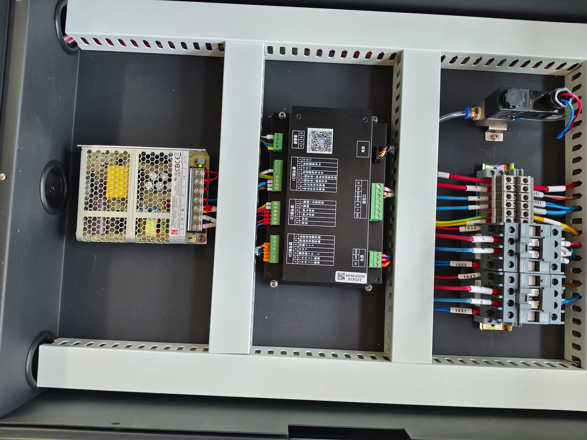
Laser welding control cabinet showing the controller, power supply and labeled electrical connections.
Machine electrical integration

Technical Resources

A useful handheld equipment record names the installed source, head, cooling arrangement and feeder, together with the compatible optics and nozzle consumables. The application record adds material, joint geometry and the accepted welding result. Keeping them connected makes later support more specific than reporting only the cabinet label or the laser wattage.

Review CHENDA Quality Control explains how configuration identification and sample evidence support acceptance. Include a photograph of the tightest welding position when discussing the head and nozzle with CHENDA.

Handheld laser welding head showing the nozzle, wire guide and attached cable assembly.
Record the head and consumable configuration

Product FAQs

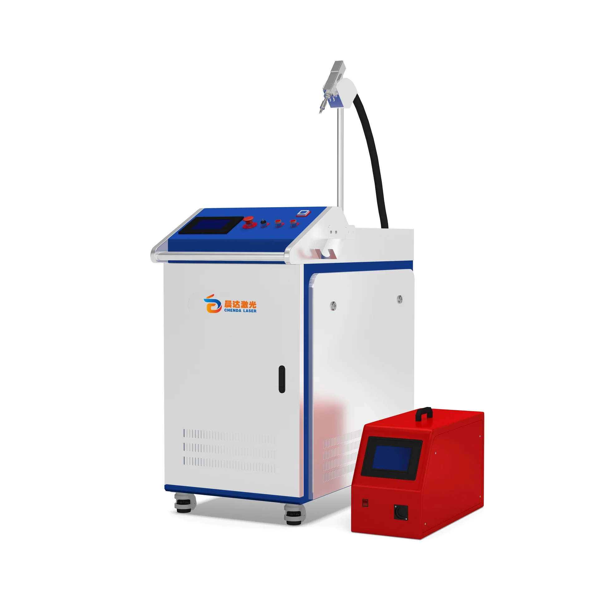
Blue and white CHENDA handheld laser welding cabinet with a welding head and external wire feeder.
Third-party laser-welded sheet-metal inside-corner sample with a continuous visible weld seam
Joint fit-up reference · smartDIYs

Can handheld laser welding bridge gaps without filler?

Only within the process window established for the joint. The acceptable gap depends on material, thickness, beam settings and the required weld section. Improve fit-up first; validate wire addition where it is appropriate.

Handheld laser head joining a sheet-metal sample

Is a higher-power machine always easier to use on thin sheet?

No. Thin-sheet welding depends on controllable energy delivery, travel speed and joint support. A larger power rating does not automatically produce a cleaner corner or prevent burn-through.

Touchscreen on a red laser welding wire feeder showing feeding controls.

Can I weld aluminum with the same settings used for stainless steel?

No. Thermal behavior, surface oxide, alloy and filler requirements differ. Submit the actual aluminum grade and joint for a separate procedure and sample assessment.

Compact gray CHENDA laser welding cabinet with an external red wire feeder.

Does handheld mean it can be used anywhere in the workshop?

No. Moving the machine does not remove laser exposure controls. Every operating location must provide suitable protection for the operator and surrounding people, including possible reflected or transmitted beams.

Touchscreen on a red laser welding wire feeder showing feeding controls.

When should I add filler wire?

When the joint design and validated procedure call for it—for example, to produce specified reinforcement or support a defined gap condition. Confirm the wire alloy as well as its diameter.

Request a Quote

Send the material grade, both component thicknesses, joint drawing, required weld length and typical batch size. Tell us whether the finished seam remains visible and whether you need a strength, sealing or dimensional result. Add the available power supply and a description of the intended welding area.

Handheld laser welding head showing the nozzle, wire guide and attached cable assembly.
Start with the tightest head-access position