CHENDA / Programmable forming

Electro-Hydraulic CNC Press Brakes

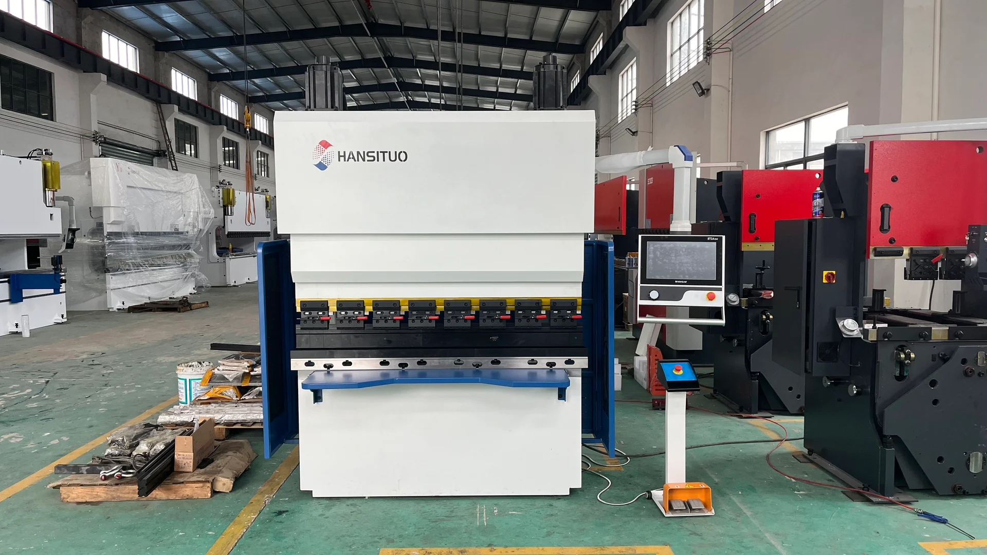
Front view of an orange and white HANSITUO CNC press brake with a side control panel.
CNC press brake · equipment reference

Product Overview

Electro-hydraulic CNC press brakes bring controlled ram synchronization, programmable gauging and bend compensation to sheet metal forming. They suit work where repeatable positioning must be combined with multiple bends, changing part geometry or long forming lengths.

CHENDA’s catalogue lists the CHD-100T/3200, CHD-200T/3200, CHD-250T/3200 and CHD-320T/3200. All four have a stated bending length of 3,200 mm, with different nominal forces. Select the force, axis package and tooling around the parts you need to produce.

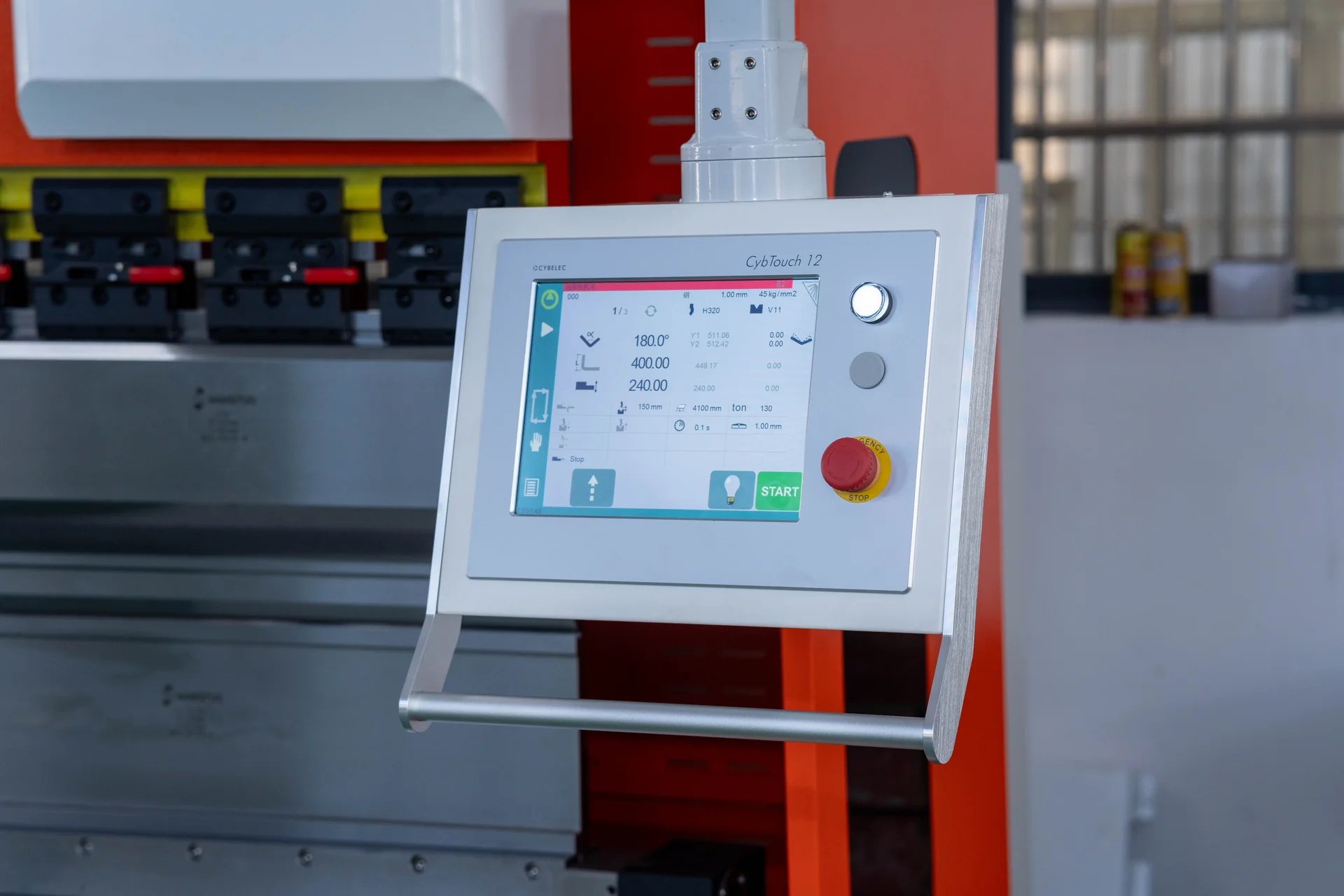
Cybelec CybTouch control panel mounted on a press brake.
Programming interface · reference

Materials & Capabilities

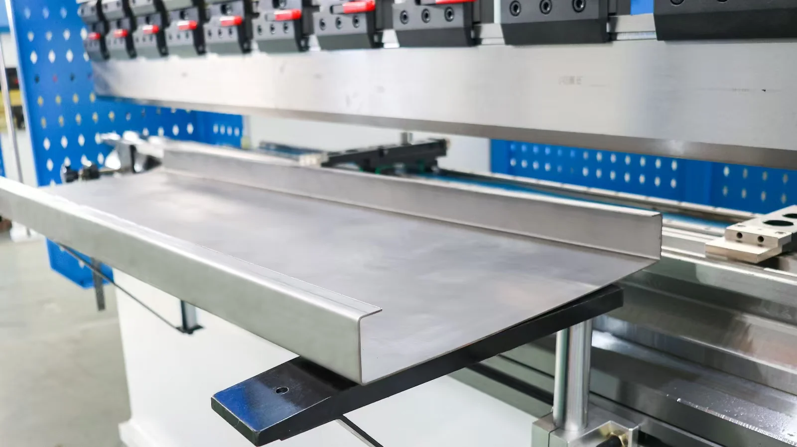
Formed sheet-metal channel resting on the front supports of a press brake.
Formed sheet geometry

Applications include steel enclosures, stainless steel panels, galvanized cabinets and aluminum formed components. The available load must be checked against grade, thickness, bend length, die opening and forming method. There is no single maximum thickness that applies to every bend across a machine’s full length.

Return flanges, offset features and deep boxes bring clearance questions as well as force requirements. Assess the punch profile, tool height, open space, throat and bend order together. Material springback and the required inside radius should be established before finalizing the flat pattern for repeated production.

For a cabinet side with a return lip, bending the main wall first may leave the lip inaccessible to the selected punch. Forming the lip earlier may preserve access but alter how the next edge reaches the gauge. The useful CNC solution therefore combines tool geometry, bend order and locating positions. Its value is a repeatable route through the entire component, not simply a stored angle for each bend.

Features close to the bend also matter. A slot or cutout that extends into the forming zone can distort as the sheet wraps over the die. That can affect a hinge, fastener or mating tab even when the overall flange is within tolerance. Tooling support, bend position or part design may need adjustment before the program is released.

Features & Engineering

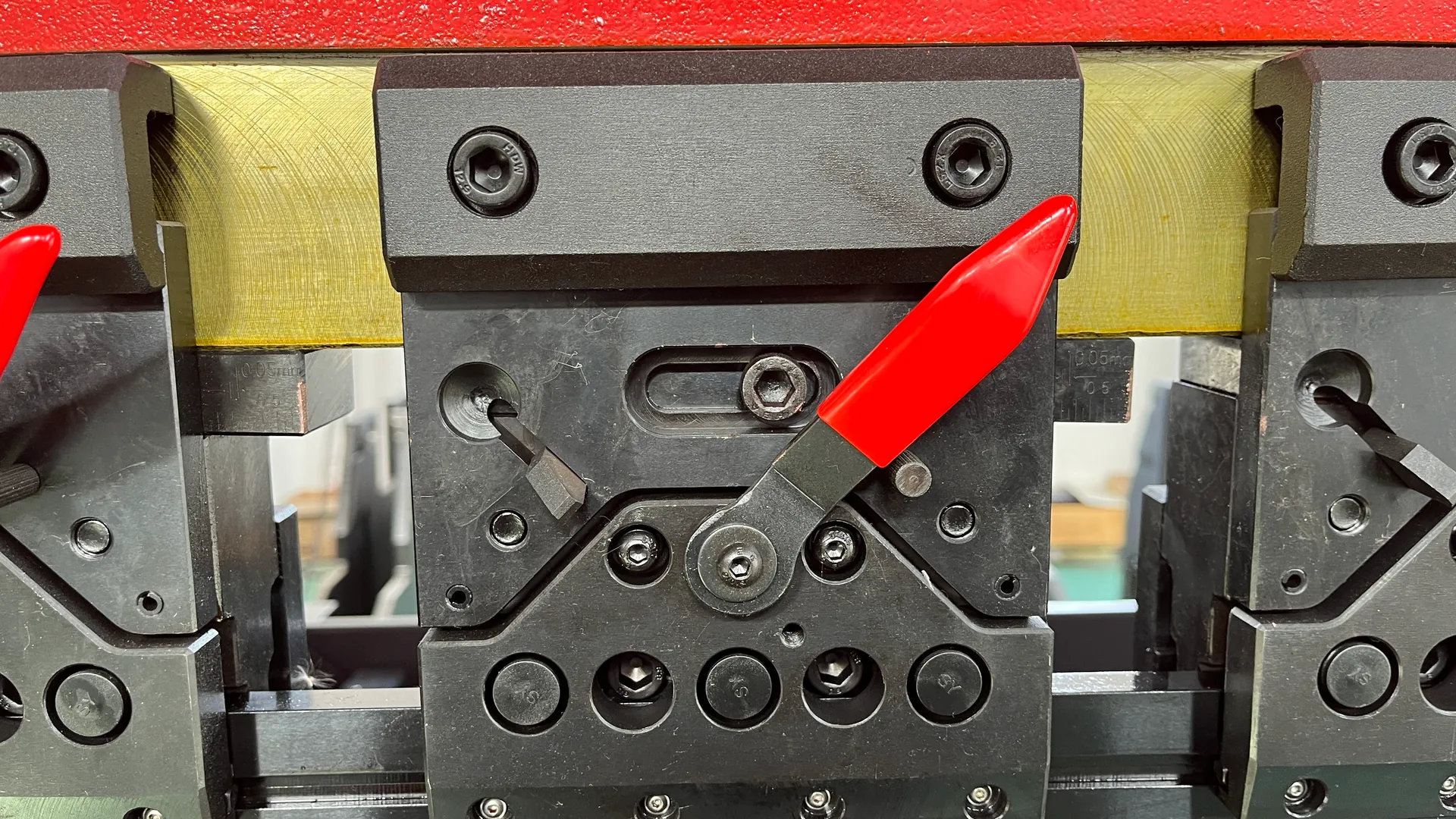
Segmented press brake tooling held by a clamp with a red release lever.
Tool interface
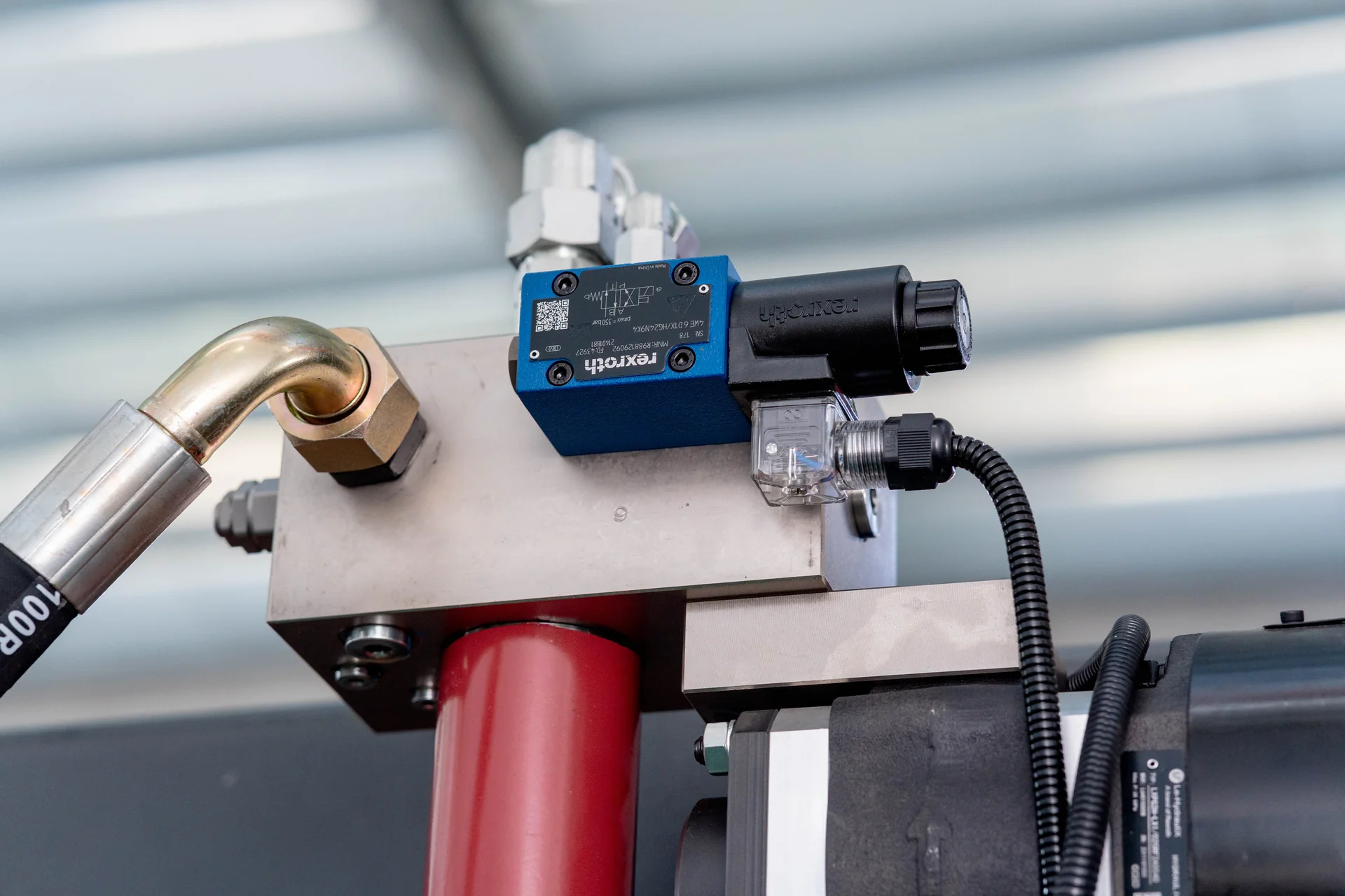
Close-up of a Rexroth hydraulic valve assembly on a press brake.
Hydraulic valve detail
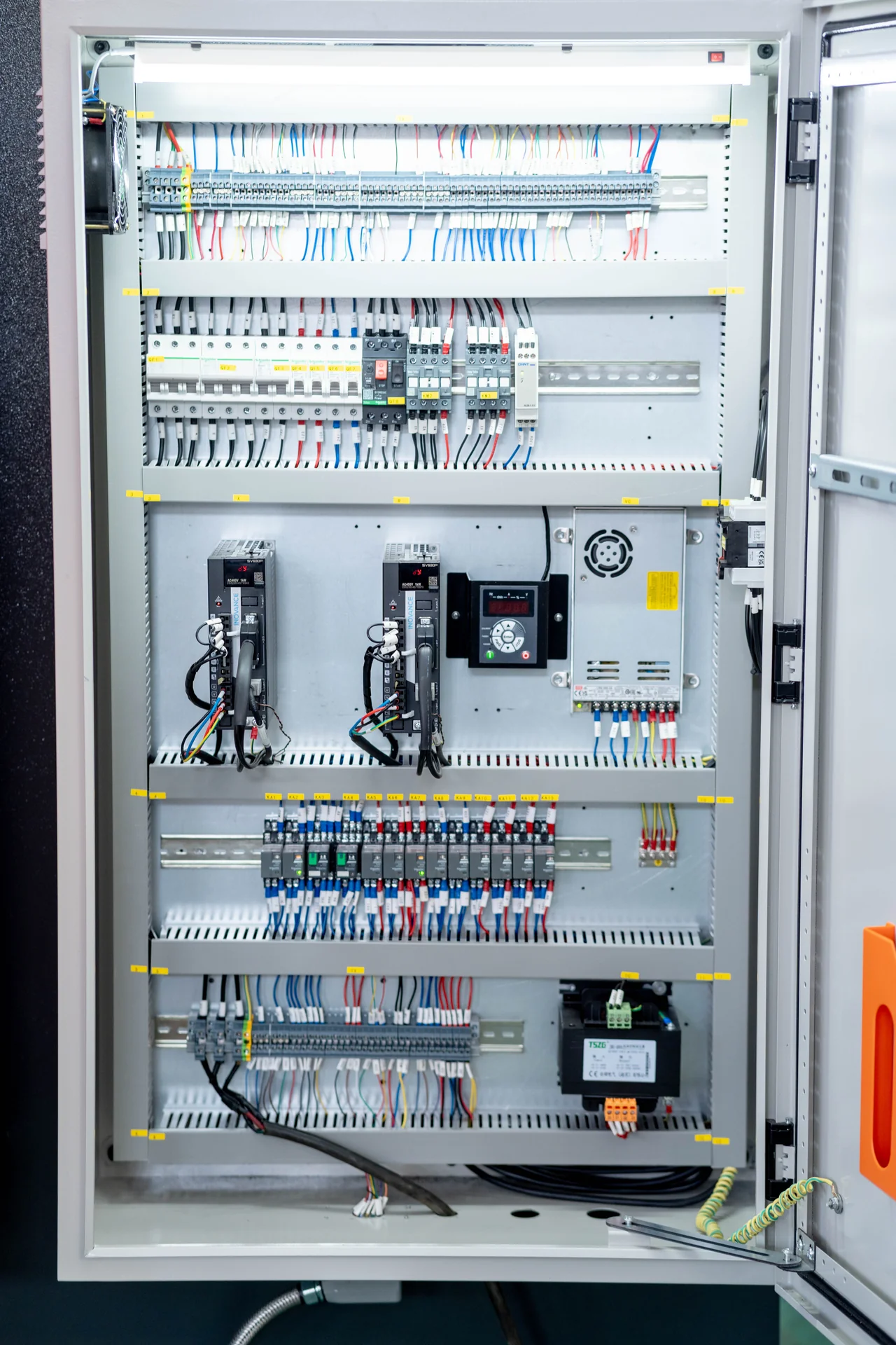
Open electrical cabinet showing labeled wiring and drives on a CNC press brake.
Electrical control cabinet

Y1/Y2 control and hydraulic motion

Electro-hydraulic synchronization controls the left and right ram sides using position feedback. The control coordinates their motion through the bending cycle. This allows the system to regulate ram alignment electronically rather than relying on a torsion-bar linkage. The specified feedback, hydraulic and control package determines the supplied implementation.

Position feedback observes machine motion; it does not directly establish the workpiece’s unloaded angle. Two material batches can follow the same ram positions and spring back differently. A stored correction can address a stable batch difference, while a separately integrated angle-measurement system may support a different feedback strategy. Those capabilities should be distinguished when comparing controls.
Compensation across long bends

The CHD catalogue describes CNC-adjusted mechanical deflection compensation. Its purpose is to counter the deflection produced under bending load so that angle variation along a long workpiece can be managed. Correct material and tool data remain necessary; compensation does not remove springback variation or repair worn tooling.

Y1/Y2 coordination and crowning act on different aspects of the geometry. Coordinating the ram ends does not eliminate elastic deflection through the middle of a long loaded span. Crowning provides a compensating profile along that span. A long panel can therefore need both functions even when the left and right position readings agree.

Formed sheet-metal channel resting on the front supports of a press brake.
Assess the angle across the complete bend
Observed bend result What to investigate before correction
Similar end angles, different center angle Deflection compensation, tool straightness, load distribution and material consistency
Similar angle error along the whole bend Material/tool data, penetration, springback and measurement method
Left-to-right trend Ram alignment, tooling seating, material thickness and the permitted loading arrangement
Correct angles, inconsistent flange size Blank dimensions, bend deduction, locating edges and gauge contact

These are diagnostic starting points, not a substitute for the machine’s service procedure. Their purpose is to avoid using one correction function to conceal a different problem.

Gauging for the next bend

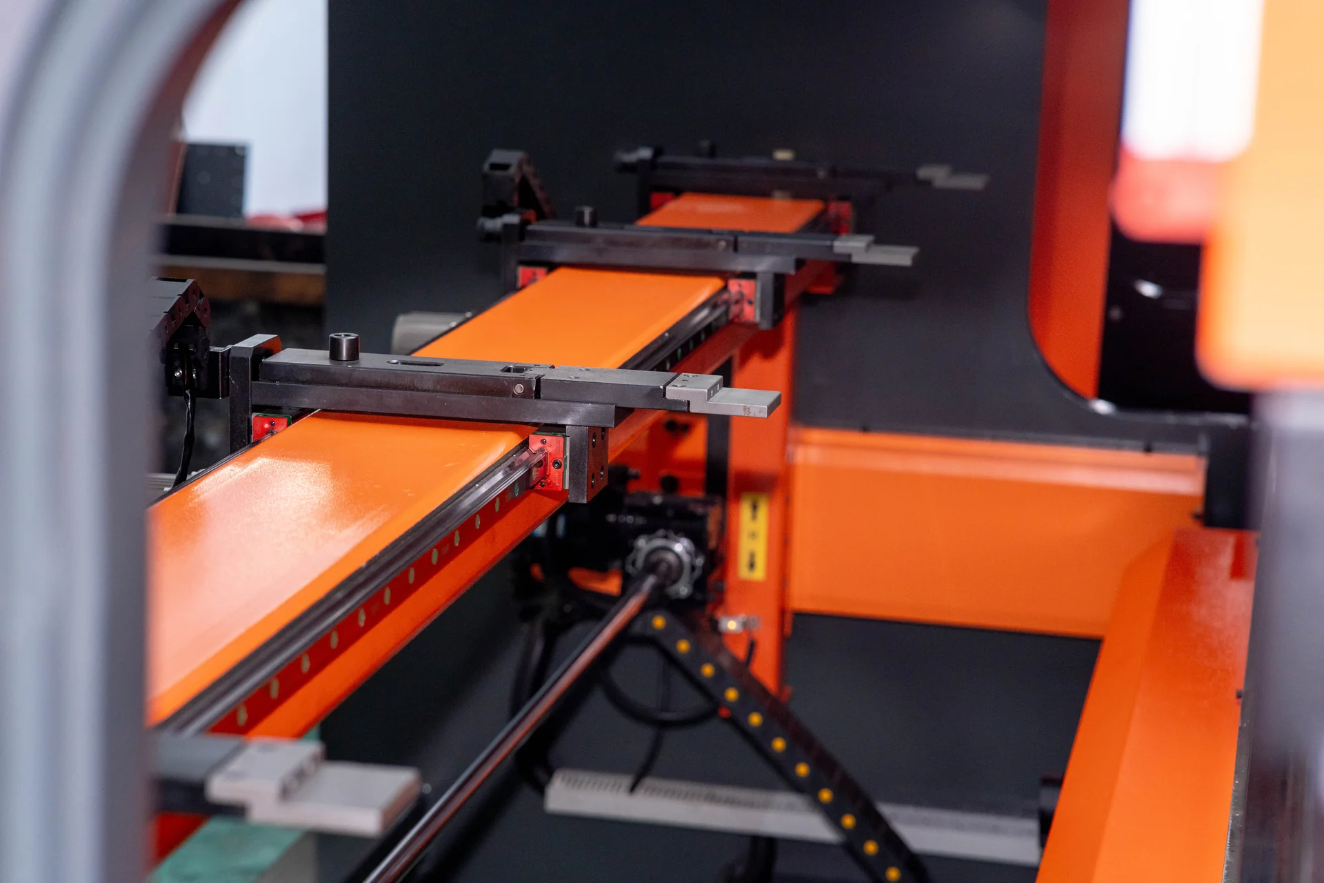
Backgauge beam, guide rails and positioning fingers inside a CNC press brake.
Backgauge positions and contact faces

An X movement sets gauge depth; an R movement changes finger height; Z movements reposition fingers along the bending line. Independent movements can help locate asymmetrical parts or clear existing flanges. The catalogue allows for different backgauge configurations, so the axis list is selected for the part sequence rather than assumed from the model name.

In a tray sequence, X can establish the required flange dimension, R can bring the contact face to a useful height after a flange has formed, and Z1/Z2 can move the fingers away from a corner cutout and onto stable locating edges. Differential depth movement, where fitted, offers a further option for angled or irregular locating edges. Lateral Z travel alone does not provide that differential depth.

Gauge fingers establish position; they should not be treated as general lifting supports for a heavy panel. A suitable front support or follower addresses the rising sheet’s weight and motion, helping the operator maintain controlled contact without forcing the part against the gauge.

Technical Specifications

The following are catalogue-listed CHD reference values. Request the current configuration sheet to confirm the supplied machine, components and order-specific dimensions.

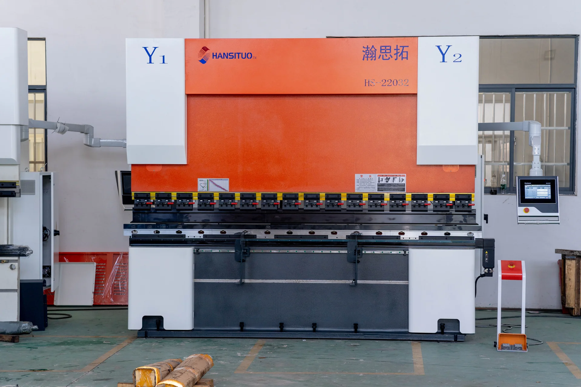
Front view of an orange and white HANSITUO CNC press brake with a side control panel.
Visual reference · to be replaced
Parameter Unit CHD-100T/3200 CHD-200T/3200 CHD-250T/3200 CHD-320T/3200
Nominal force kN 1,000 2,000 2,500 3,200
Bending length mm 3,200 3,200 3,200 3,200
Distance between uprights mm 2,700 2,700 2,700 2,700
Throat depth mm 400 400 400 400
Ram stroke mm 200 200 200 200
Worktable height mm 800 800 800 800
Listed power kW 7.5 15 15 18.5

The force values are reproduced in kN; the “T” in each model name is a designation, not a separate precision conversion. Listed power is not a complete electrical installation specification or a measure of energy consumed per part.

Confirm open height using a dimensioned drawing with the proposed holders, punch and die. Also request the backgauge travel by axis, controller functions, working speed, tooling load limits, machine mass and installation requirements. Finished angle and flange tolerances should be agreed on a representative part under stated conditions.

The four models share the listed working length, throat and ram stroke. Choosing the higher-force version therefore increases the stated force but does not, by itself, open more room for a deep box. A taller punch may provide return-flange clearance while consuming more of the open height. The tool stack and part-removal path remain separate checks from the force calculation.

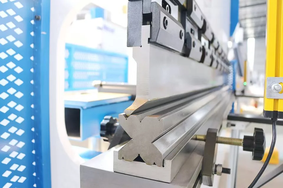
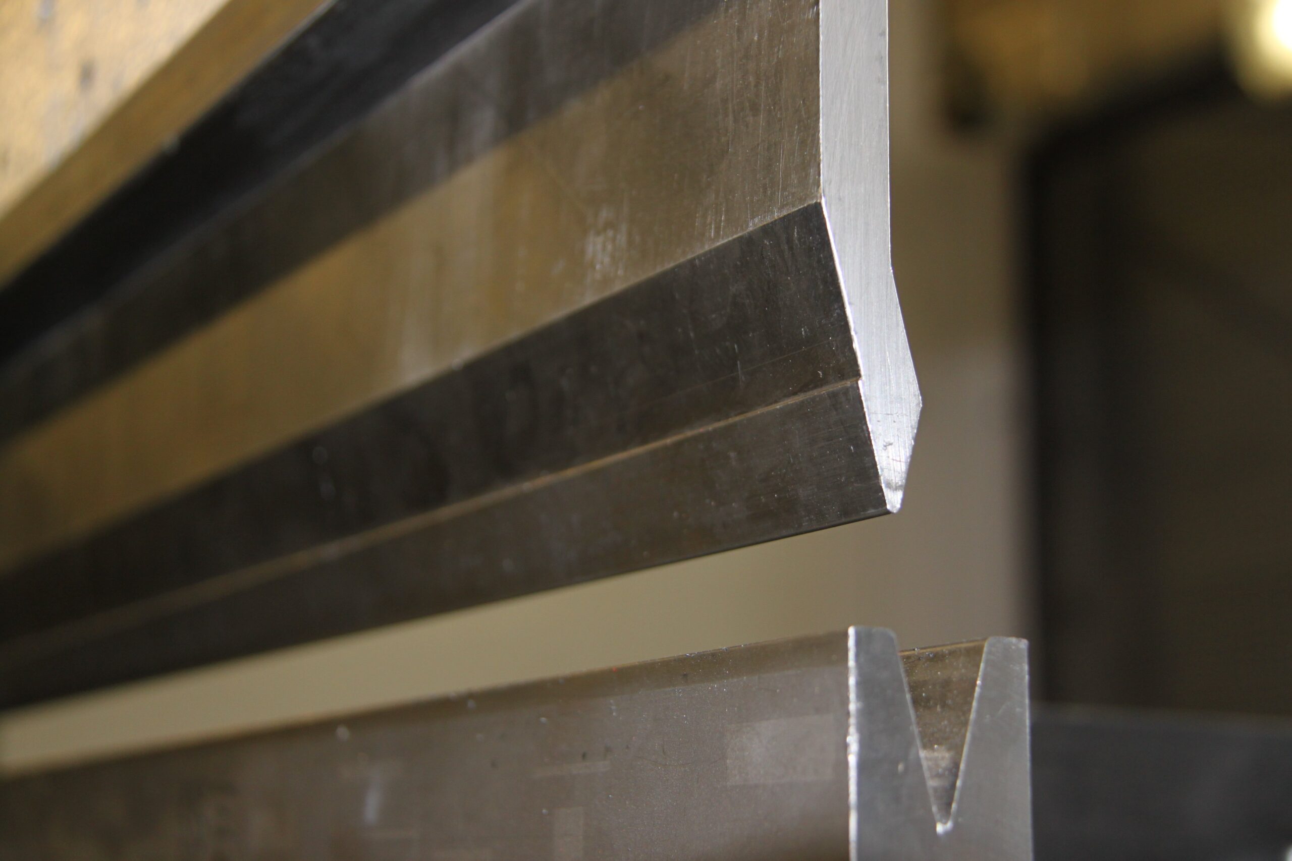
Close-up photograph of press brake punch and V-die tooling
Check tooling access through the whole sequence · Contour (uploaded by Jasper84) · CC0 1.0

Samples & Demonstration

For enclosure work, request a sample that combines a long bend with a return flange or box corner. It should show whether the tools clear the workpiece, the fingers can locate it and the sequence leaves a practical route for removal.

Measure angle at the ends and middle of a long bend after unloading. Check flange dimensions and corner fit, then repeat the part using the same material and setup. When comparing configurations, include programming, gauging and handling time in the demonstration alongside ram movement.

For the return-lip example, the evaluation should show the complete sequence, including the last bend and removal of the finished part. Record which edge touches which gauge face at every step. An attractive simulation is useful only when its tool profiles, holders, part orientation and machine clearances represent the physical setup. The quality-control process explains how those details can be tied to an agreed part and inspection record.

Configuration & Options

The CHD catalogue describes a welded, stress-relieved structure, CNC-adjusted mechanical compensation and configurable backgauging. The current proposal establishes the actual build and included equipment.

Segmented press brake tooling held by a clamp with a red release lever.
Visual reference · to be replaced
Cybelec CybTouch control panel mounted on a press brake.
Visual reference · to be replaced
Configuration area Discuss for your production
Controller and programming Numerical, 2D or 3D workflow; tool library; sequence checking; file compatibility
Backgauge Required X, R and Z movements; finger shape; reach; manual versus controlled adjustment
Clamping and tooling Compatible tool interface, segmented punches, selected die openings and quick-change options
Compensation Adjustment range and operation matched to the machine and forming load
Part handling Front supports or followers for wide, heavy or surface-sensitive panels
Protective functions Front, side and rear access arrangements matched to the application and destination

Offline programming and angle measurement are separate functions to discuss where they add value; they are not implied by the term CNC. Component brands and software licenses are specified in the quotation.

For frequent changeovers, compatible clamping can shorten the time spent rebuilding tool stations. For long visible panels, appropriate support and a tool-contact strategy may matter more. For parts with returns, a gooseneck or special punch can create clearance, but its load rating must still cover the bend. The most useful option is the one that resolves a specific limitation in the job.

Applications & Workflow

For electrical cabinets, form the features that preserve later tool access before closing the box. Use a consistent blank datum, and choose gauge contacts that avoid holes, burr or unstable edges. Tool stations can reduce changes between bends where the machine, tool lengths and part sequence permit them.

For mixed fabrication, maintain a controlled library of material, tool and program information. Inspect the first component after a material or tool change, then save the accepted correction with the relevant job setup. This links the programmed sequence to a measured production result.

Painted metal filing cabinets with open drawers
Cabinet production · application reference

Installation & Support

Open electrical cabinet showing labeled wiring and drives on a CNC press brake.
Electrical installation detail · reference

Prepare the floor, lifting route and electrical connection from the selected machine’s layout. Include space for long panels to rotate, access to the rear gauge and removal of tools. Hydraulic oil specification and filling requirements are machine-specific.

Commissioning should address reference positions, axis movements, tool data, compensation and protective functions before the agreed trial part. Training should cover sequence review, corrections, backups and the distinction between a programmed tool model and the physical tool installed.

Tool libraries, accepted sample programs and machine-specific parameters serve different purposes and should be identified accordingly at handover. The production and delivery route helps define which files, tools, accessories and records travel with the equipment. Preserve the accepted baseline before introducing new jobs, so service can compare a reported problem with a known setup.

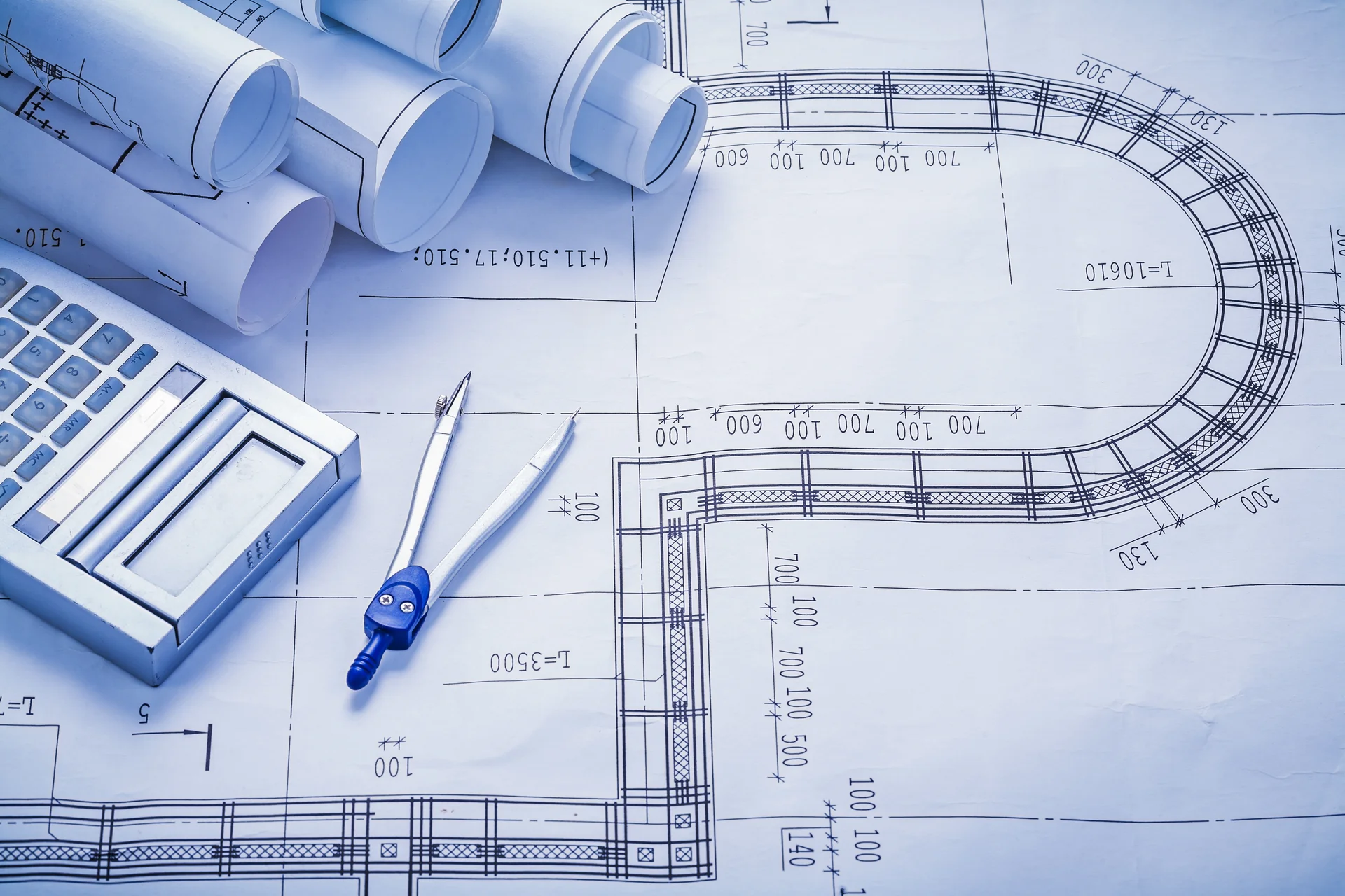
Technical drawings with a calculator and drafting compass
Part and axis review · reference

Technical Resources

Request a CHD model sheet, axis schedule, general arrangement drawing and tooling proposal. For box parts, include a section view or 3D file so the review can consider return flanges and removal clearance.

Product FAQs

Backgauge beam, guide rails and positioning fingers inside a CNC press brake.
Gauging detail
Backgauge beam, guide rails and positioning fingers inside a CNC press brake.
Visual reference · to be replaced

What does “6+1 axes” mean?

Naming conventions vary. A package may count Y1, Y2, X, R, Z1 and Z2 as six controlled axes, with crowning as an additional function. Request the actual list; the count alone does not describe travel or capability.

Cybelec CybTouch control panel mounted on a press brake.
Visual reference · to be replaced

Does CNC crowning automatically measure the bend angle?

No. Programmed compensation and angle measurement are different functions. Crowning may use calculated settings without measuring the finished angle. A measuring system, if proposed, needs its own scope and operating conditions.

Close-up of a press brake punch aligned with a multi-V lower die.
Visual reference · to be replaced

Can a higher-force model make the same short flange?

More machine force does not solve tool clearance or flange-support limits. Check the die opening, punch geometry, material and tooling load. A narrower die can increase force demand and surface pressure.

Formed sheet-metal channel resting on the front supports of a press brake.
Visual reference · to be replaced

Can the 3,200 mm model form any part of that length?

The stated working length is one constraint. Required force, upright clearance, throat, tooling, bend sequence and part handling can impose additional limits. Evaluate the complete geometry.

Request a Quote

Send material grade, thickness, bend length, target angles, inside radii and the complete part drawing. Identify deep returns, critical flange tolerances, normal batch size and any tooling or controller preference. CHENDA will use these inputs to discuss the model and configuration.

Formed sheet-metal channel resting on the front supports of a press brake.
Define the finished bend