Servo-electric / Sheet metal forming

Electric Press Brakes for Responsive Sheet Metal Forming

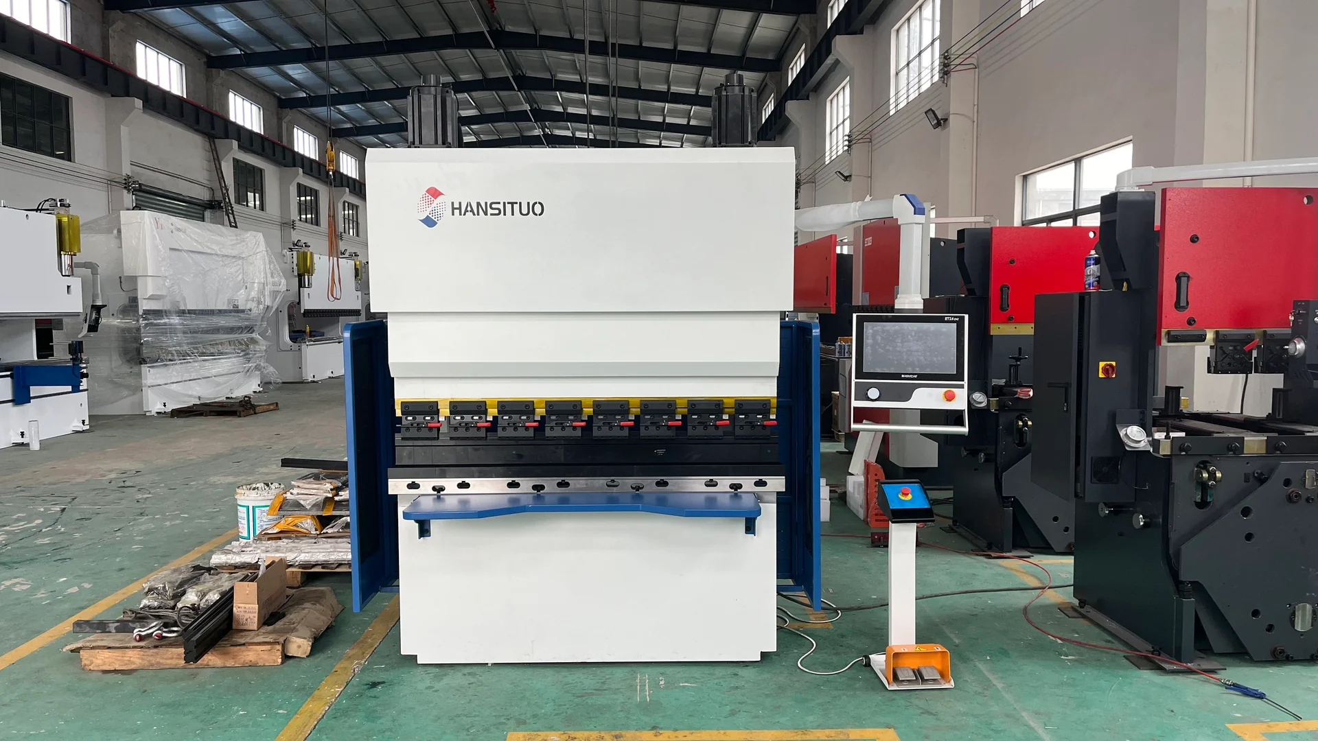
Compact HANSITUO electric press brake with visible upper drive motors and front supports.
Electric press brake · equipment reference
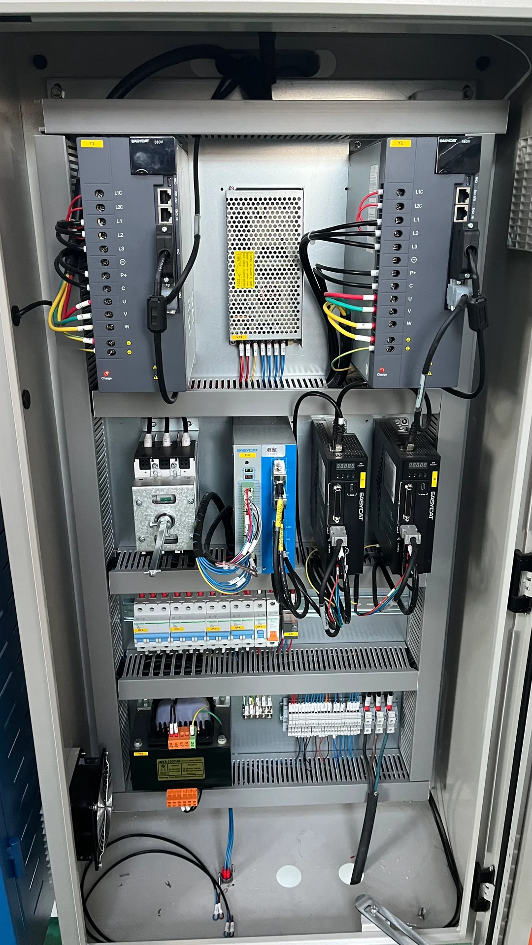
Electrical cabinet with paired drive units inside an electric press brake.
Electrical drive cabinet · reference

Product Overview

An electric press brake uses servo motors and a mechanical transmission to generate forming motion. For suitable parts, this creates a responsive bending station without a hydraulic ram-drive circuit. It is an equipment direction to evaluate for repeated brackets, covers and other sheet metal components where handling, motion and changeover determine output.

CHENDA can discuss an electric press-brake configuration around your force, bend length and production cycle. The useful comparison starts with a complete part: several bends, the required repositioning and the time needed to load and remove it.

Materials & Capabilities

Electric drive changes how force reaches the ram; it does not change the material’s forming limits. Steel, stainless steel, galvanized sheet and aluminum components still require compatible tooling, sufficient force and a suitable bend radius. Material grade, temper and grain direction remain relevant to cracking and springback.

The route is particularly worth evaluating when the regular workload consists of components that operators can locate and turn efficiently. A short bracket may benefit from a compact work area, while a wide panel may need supports and additional handling clearance. Long or thick parts require their own load and duty assessment rather than an assumption based on the drive type.

For a small equipment cover with several short flanges, the machine must provide room for the operator to hold the part and for the formed returns to clear the punch. An apparently small component can be awkward if the last flange blocks the gauge or traps the work around the tool. Tool segmentation and an accessible sequence solve that geometry; faster ram travel does not.

Part size also affects where the work should happen. Placing the regular tool station near the operator’s natural working position can reduce reach and repeated repositioning. Short blanks need usable finger contact and a clear view of the bend; wide thin panels need support that does not scratch the visible surface. These details turn drive response into useful production time.

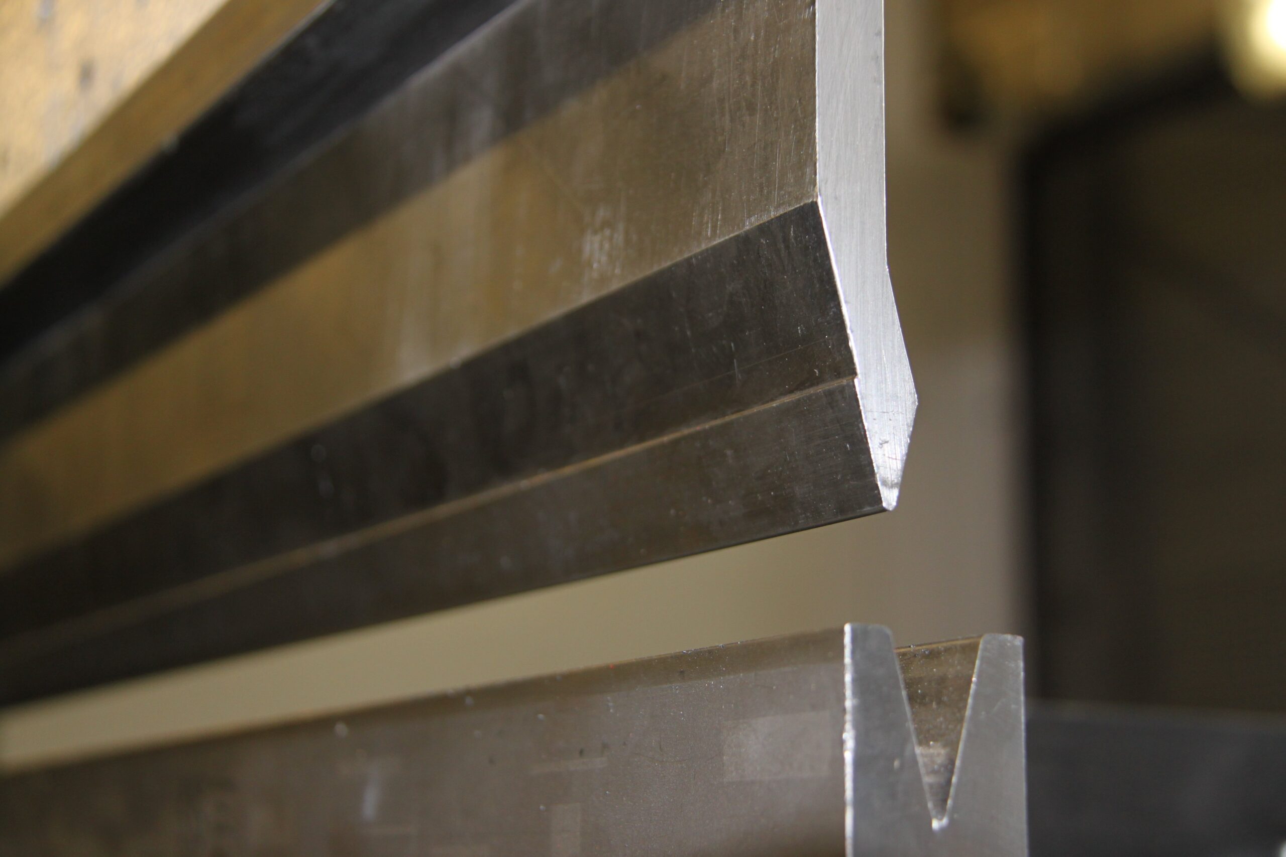
Close-up photograph of press brake punch and V-die tooling
Material forming still depends on the tooling · Contour (uploaded by Jasper84) · CC0 1.0

Features & Engineering

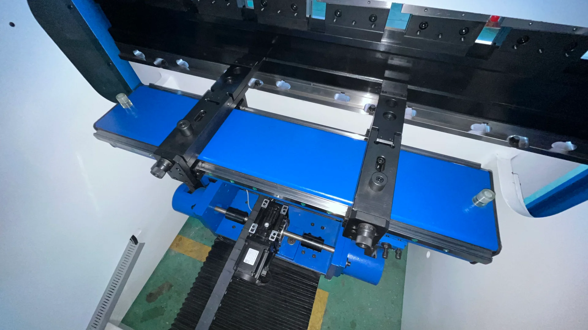
Backgauge fingers and guide rails inside a compact electric press brake.
Electric-machine backgauge

Servo motion with a defined load path

Servo-electric designs use a mechanical transmission, which may involve screws, belts or another arrangement specified by the manufacturer. The transmission, feedback and frame work together to produce the required force and movement. Request the actual drive arrangement because maintenance points and loading limits vary by design.
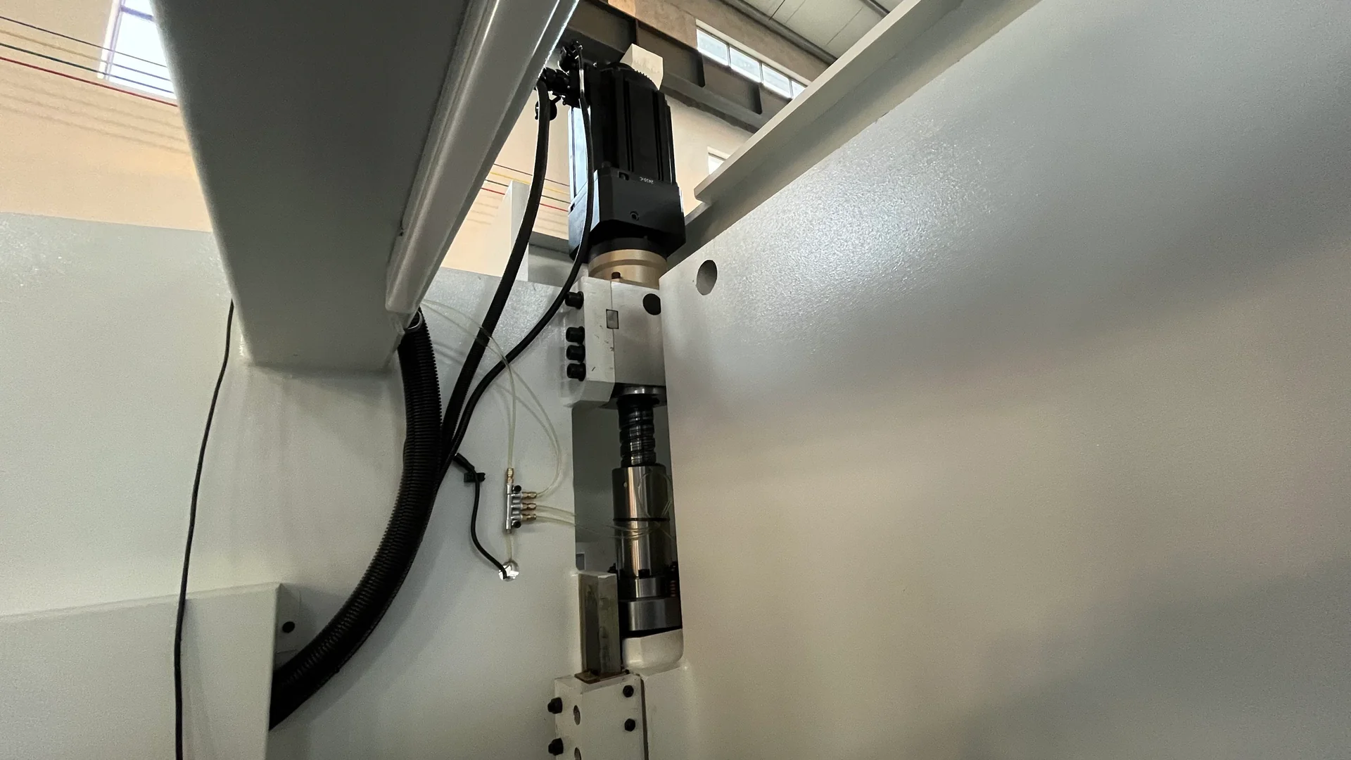
Internal screw drive and motor assembly of an electric press brake.
Mechanical load path · reference
Drive description How the main forming force is produced Practical distinction
Servo-electric Motor torque reaches the ram through a mechanical transmission or specified direct-drive arrangement Forming performance depends on that transmission, frame and servo control
Servo-hydraulic A servo-driven pump supplies hydraulic actuation Still has a hydraulic forming circuit and its fluid-related requirements
Hybrid hydraulic arrangements Electric motor and hydraulic functions are combined in a defined architecture The label alone does not identify the load path or included subsystems

For electric equipment, control of acceleration and the transition into forming can be as relevant as maximum speed. A short stroke may never spend much time at the advertised peak velocity. The useful result is controlled contact with the material, sufficient force through the working movement and a return opening appropriate to the next handling step.
Motion is only part of the cycle

Approach, working and return movements serve different purposes. Fast approach can reduce non-forming time, but the operator must still locate the blank, support it and turn it for the next bend. A useful station combines appropriate motion with accessible gauge fingers, well-positioned tools and comfortable handling.

Opening the ram farther than the part needs adds travel on every cycle. Opening too little can obstruct rotation or removal. A part-specific return position, where the control supports it, balances those requirements. The same thinking applies to the gauge: a shorter movement is useful only when the fingers still clear the formed part and reach the next datum.

Backgauge fingers and guide rails inside a compact electric press brake.
Gauging and clearance during the cycle
Electrical cabinet with paired drive units inside an electric press brake.
Electrical drive cabinet · reference

A different maintenance profile

Removing the main hydraulic forming circuit removes its oil and filtration tasks. Mechanical transmission, guides, bearings, lubrication, protective functions and electrical components still need inspection. “Electric” does not mean maintenance-free, and any auxiliary hydraulic tooling system should be identified separately.

The duty profile belongs in the mechanical assessment. Repeated high-load bends, frequent acceleration and long idle periods create different demands from occasional heavy work. A model’s nominal force is one boundary; the permitted cycle, load distribution and operating conditions establish how that force can be used in production. These limits are specific to the supplied design, not a universal restriction on all electric machines.

Technical Specifications

Select an electric machine from the normal part mix as well as the heaviest bend. The quoted data should describe the exact drive and axis package.

Compact HANSITUO electric press brake with visible upper drive motors and front supports.
Visual reference · to be replaced
Specification Unit or format Why it matters
Nominal force kN Forming capacity under the stated load-distribution conditions
Bending length mm Available working length for the selected tools
Ram stroke / daylight mm / mm Motion range and open tool-stack clearance
Throat / upright spacing mm / mm Passage for returns, deep parts and wider panels
Approach, working and return speeds mm/s, stated separately Motion characteristics at each stage of a cycle
Backgauge axes and travel Named axes; mm Locating and repositioning capability
Drive system Transmission type and motor ratings in kW Construction, electrical demand and maintenance requirements
Duty conditions Cycle, load and operating pattern Suitability for the planned sustained workload
Energy consumption kWh for a defined job or operating period Comparison that includes idle time, auxiliaries and accepted output

An axis positioning specification is not a guaranteed part-angle tolerance. Specify the finished geometry and verify it with the intended material and tooling. Similarly, installed motor power and measured energy per accepted component answer different questions.

A complete-cycle calculation

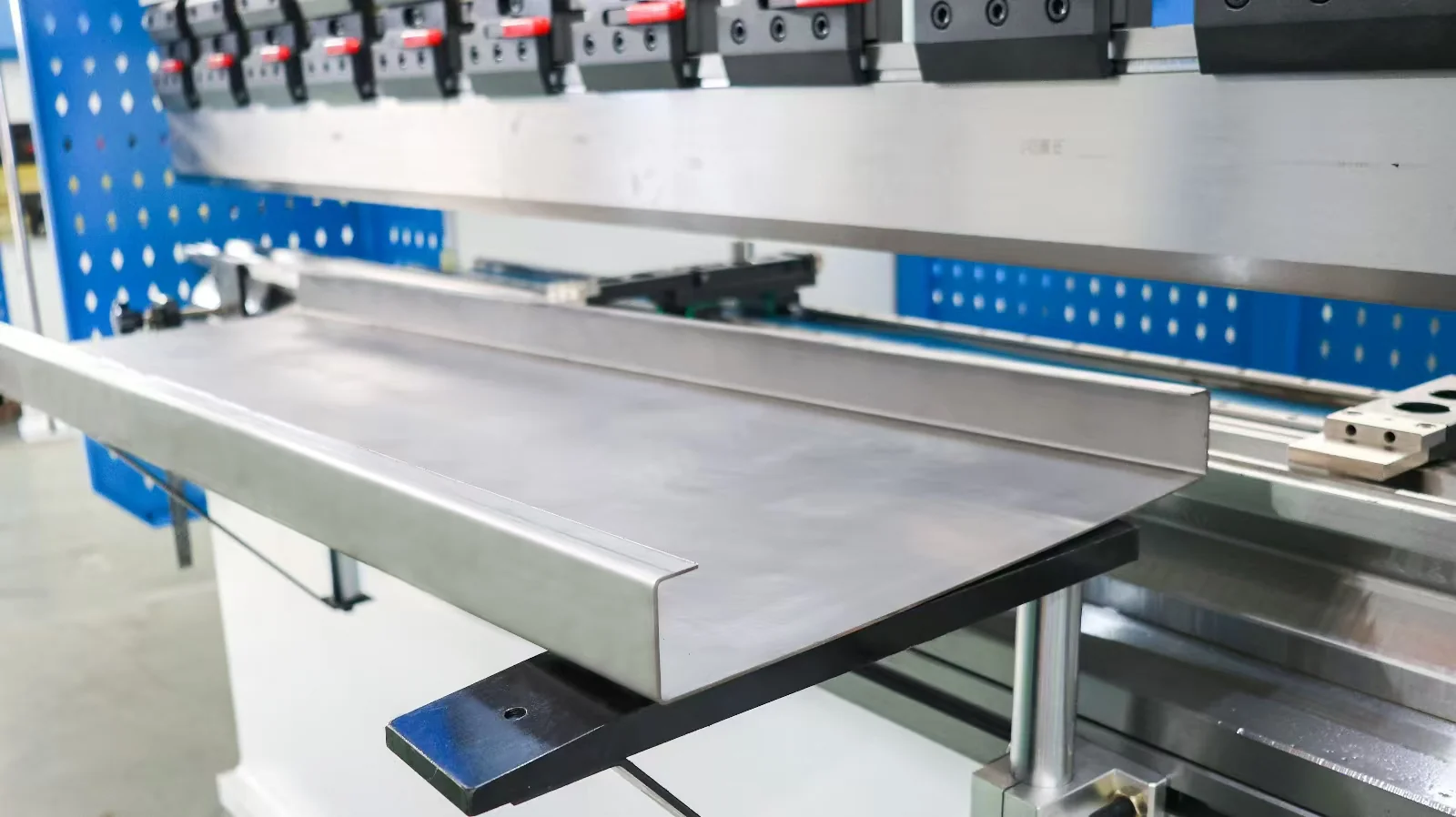
Formed sheet-metal channel resting on the front supports of a press brake.
Evaluate the complete finished part
Illustrative cycle30 s
20 s handling10 s motion
With 20% less motion time28 s
20 s handling8 s motion

Consider an illustrative 30-second part cycle made up of 20 seconds of loading, locating, turning and removal plus 10 seconds of machine movement. Reducing the movement portion by 20% saves 2 seconds, making the complete cycle 28 seconds. The complete-cycle reduction is about 6.7%, not 20%. These assumed numbers demonstrate the calculation; they are not a CHENDA speed claim.

This is why a small-parts station should be evaluated as a workplace as well as a drive system. Clear bin positions, suitable tool stations and reliable gauge contact may complement faster motion. Any comparison should use accepted parts and preserve the same material, bend sequence and inspection requirement.

Samples & Demonstration

Formed sheet-metal channel resting on the front supports of a press brake.
Inspect flange size, angle and assembly fit

For a repeat bracket, a meaningful demonstration includes blank pickup, location, each bend, part rotation, removal and inspection. Record accepted pieces over an agreed interval rather than deriving production output from maximum ram speed.

Use an additional part with the deepest return or shortest flange to test clearance. If energy performance drives the purchase, agree the measurement boundary, production cycle, waiting periods and auxiliary loads. Compare the same finished parts under comparable conditions; a generic saving percentage cannot describe every workload.

For a repeated electronics bracket, include a return to the job after another program has run. This reveals whether the operator can reproduce the tool positions and correct gauge contacts, rather than merely repeat uninterrupted strokes. Measure the hole-to-flange relationship or another functional assembly dimension along with the angle. CHENDA’s quality-control framework connects the proposed demonstration with a defined configuration and recorded result.

Configuration & Options

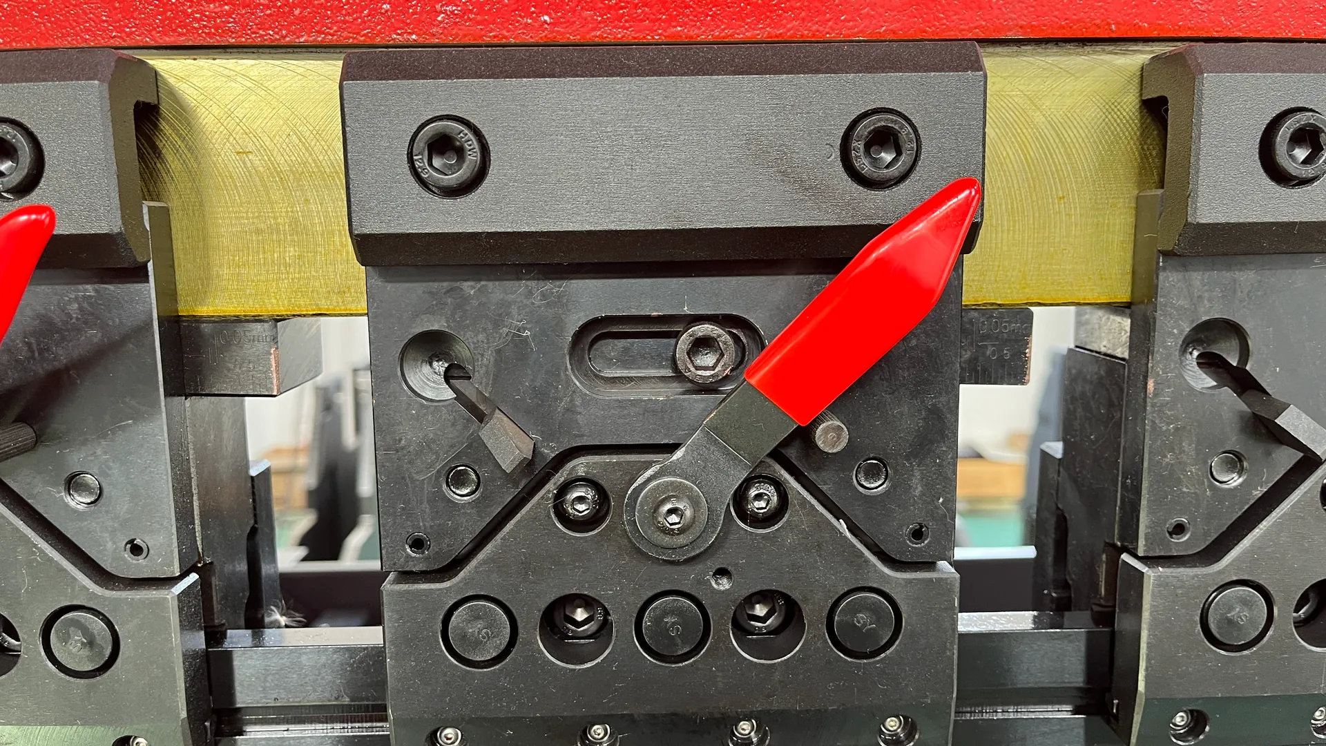
Segmented press brake tooling held by a clamp with a red release lever.
Tool stations and clamping

Discuss the following according to the station’s intended use:

  • Working position: machine height, front clearance, part supports and operator access suited to the regular component size.
  • Gauging: automatic depth and finger-height movements, lateral finger positions and contact shapes.
  • Tooling and clamping: segmented tooling, compatible holders and changeover method for the required profiles.
  • Control: part programming, tool data, sequence display and supported transfer of production information.
  • Compensation and measurement: the proposed deflection adjustment and any separate angle-measurement function.
  • Automation interface: only where loading, gripping, gauging and protective functions are designed together.
Backgauge fingers and guide rails inside a compact electric press brake.
Gauge fingers and working access

Options are selected as a package. A controller feature does not establish that the corresponding mechanical axis or sensor is installed.

A support table that helps a short blank can obstruct a deep part if its position is unsuitable. A faster clamp is most valuable when tools actually change often. A rotary or special locating accessory needs room within the working envelope. Evaluating these interfaces on the main part family prevents a long option list from creating a less usable station.

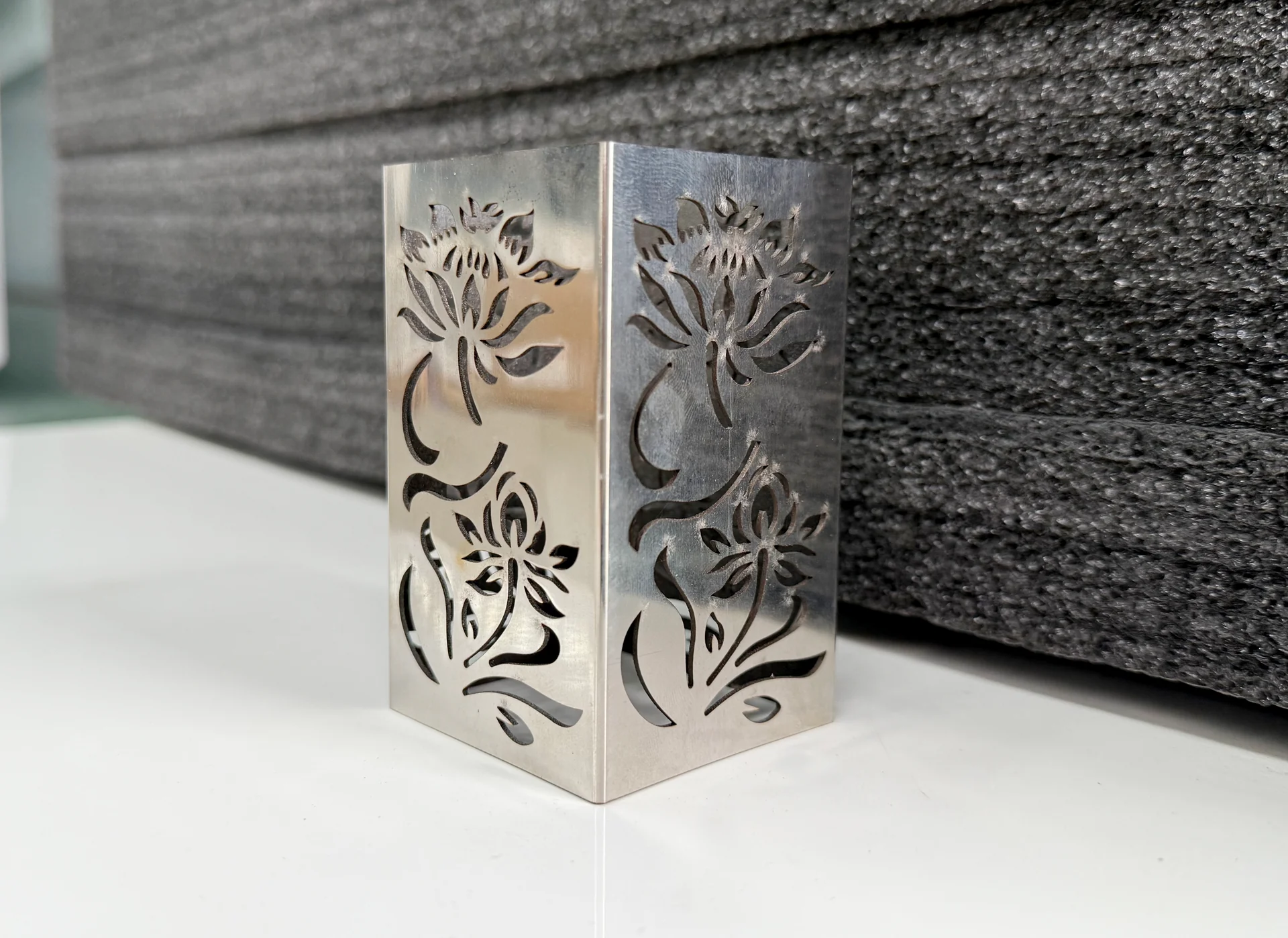
Bent metal panel with floral cutouts across two adjoining faces
Formed sheet component reference

Applications & Workflow

A dedicated bracket station can keep frequently used tools in position, store the accepted bend program and present blanks within easy reach. Consistent orientation at the gauge helps maintain flange dimensions. Inspect the first piece when material, tools or the program changes, then monitor the features that affect assembly.

For small covers and trays, organize the sequence so that earlier flanges leave access for later bends. Tool segmentation and clearance can matter more than nominal machine force. For metal furniture and cabinet components, include visible-surface inspection and a handling method that avoids dragging parts across abrasive surfaces.

For mixed small-batch work, group components by compatible tooling where that does not confuse material or drawing identity. Keep the accepted program linked to its tool setup and first-piece result. The benefit is less time rediscovering a working process at the next order. When a part changes, update the sequence and tooling information together instead of treating the stored program as proof that the new geometry will clear.

Installation & Support

Electrical cabinet with paired drive units inside an electric press brake.
Drive cabinet · installation reference

Confirm machine mass, floor conditions, electrical supply, grounding and clearances from the selected model’s installation information. Space for tools, bins and operator movement belongs in the layout alongside the machine itself.

Training should address drive and axis references, tooling data, force limits, first-piece correction, lubrication and program backup. If a servo or position alarm occurs, retain the alarm details and operating condition for diagnosis; recovery follows the supplied machine procedure.

Before dispatch, identify the supplied tools, support accessories, software modules and backups in the handover scope. The production and delivery process provides a route for keeping those items aligned with the selected configuration. On receipt, a representative bracket or cover gives operators a practical job on which to learn the setup and inspection sequence.

Technical Resources

Request the current electric-machine data sheet, drive description, dimensioned layout and maintenance schedule. Include your intended cycle and load pattern when requesting an energy or productivity comparison.

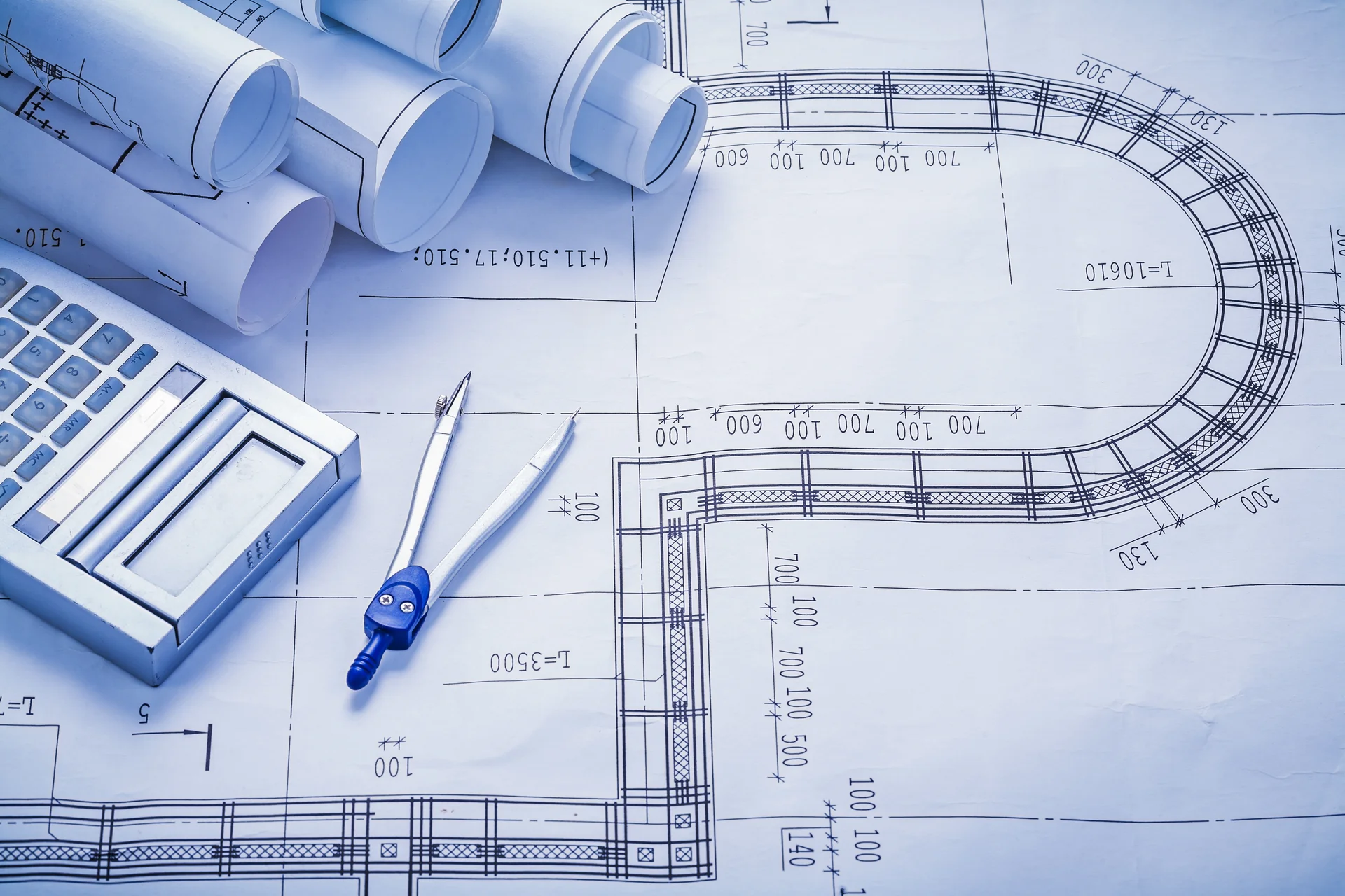
Technical drawings with a calculator and drafting compass
Review the duty cycle and layout

Product FAQs

Internal screw drive and motor assembly of an electric press brake.
Servo transmission detail
Internal screw drive and motor assembly of an electric press brake.
Visual reference · to be replaced

Is a servo-hydraulic press brake the same as an electric press brake?

No. A servo-hydraulic design uses a servo motor in its hydraulic drive arrangement. A servo-electric forming drive transmits force mechanically without using hydraulic cylinders for the main bending action. Ask which architecture the quotation specifies.

Electrical cabinet with paired drive units inside an electric press brake.
Visual reference · to be replaced

How much electricity will it save?

That depends on the compared machines, load, cycle, idle time and auxiliary equipment. Request a measured or clearly defined calculation for your workload. Motor ratings alone do not establish the saving.

Backgauge fingers and guide rails inside a compact electric press brake.
Visual reference · to be replaced

Does electric drive make a small part faster to produce?

It may reduce portions of machine motion, but handling and the bend sequence may dominate. Compare complete cycle time and accepted output, including any necessary repositioning and inspection.

Segmented press brake tooling held by a clamp with a red release lever.
Visual reference · to be replaced

Can we reuse tooling from a hydraulic press brake?

Possibly, if the tool interface, height, load rating, clamping and clearance are compatible. Supply the tool drawings or measured dimensions for review before including reuse in the project scope.

Electrical cabinet with paired drive units inside an electric press brake.
Visual reference · to be replaced

Does the machine need no oil at all?

A main hydraulic circuit is absent in a fully electric forming drive, but lubrication remains necessary and separately specified auxiliary systems may use fluid. Follow the configuration-specific maintenance schedule.

Request a Quote

Send the drawing, material, thickness, bend length and expected output. Identify the normal number of bends per part, changeover frequency, handling method and available floor space. If energy is a priority, include the current machine and operating pattern for a meaningful comparison.

Formed sheet-metal channel resting on the front supports of a press brake.
Define your normal part and cycle