CHENDA / Applications

Industrial Equipment by Manufacturing Application

If you are comparing equipment for a real production job, start with the material, the workpiece and the complete process – not with a machine specification in isolation. CHENDA supplies equipment categories for metal cutting, forming, welding, cleaning, marking and finishing, together with digital knife cutting for flexible and non-metallic sheet materials. This application guide helps manufacturers identify the right equipment direction before discussing a configuration.

The six application areas below reflect different production problems. Sheet metal and steel structure work usually require a connected metal-fabrication route. Metal furniture, cabinets, signs and displays add strong appearance and fit requirements. Packaging, textiles and upholstery depend more heavily on digital files, material hold-down and the correct knife or creasing tool. In every case, a representative drawing and material sample are more useful than a general industry label.

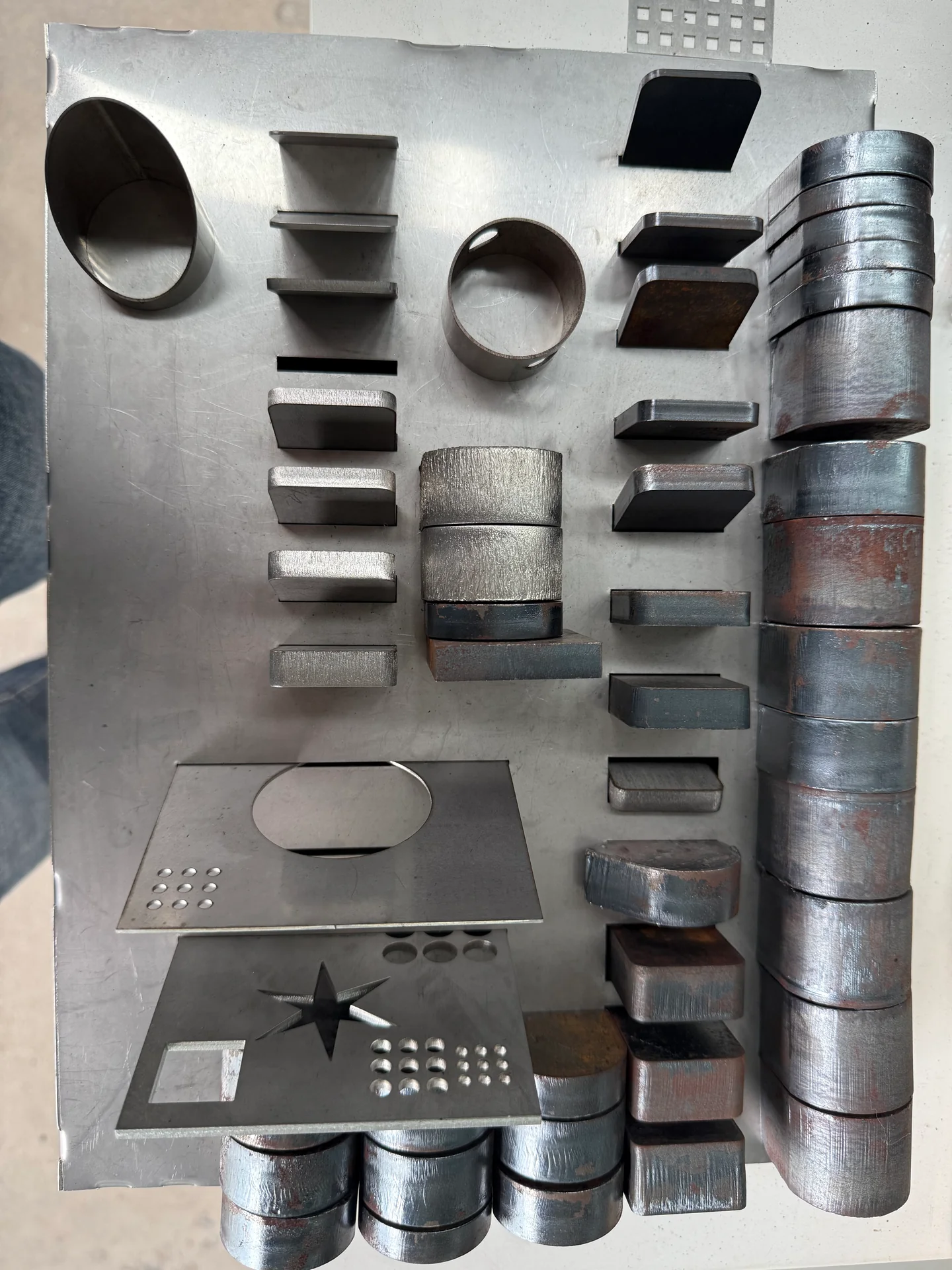
Cut metal profiles and plate edges showing different workpiece forms
Metal workpieces
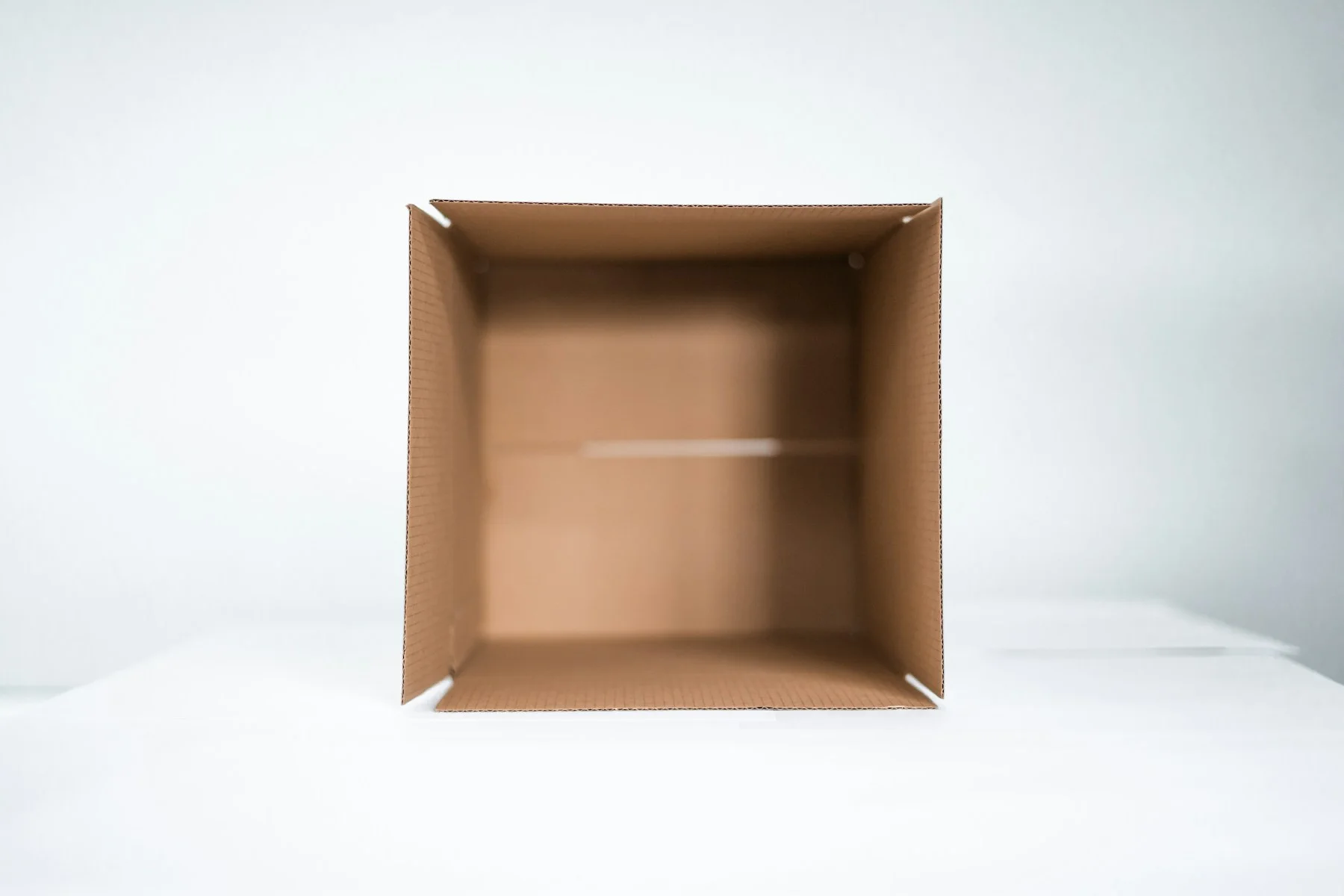
Open folded cardboard box; packaging reference
Packaging structures · reference
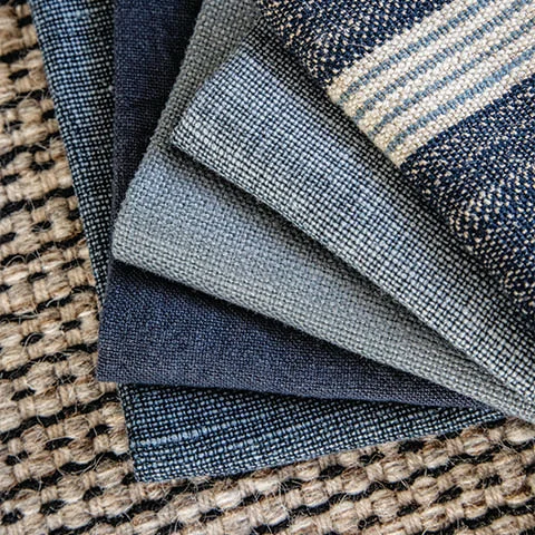
Blue and grey woven upholstery fabric swatches; reference
Flexible materials · reference

Find Your Application

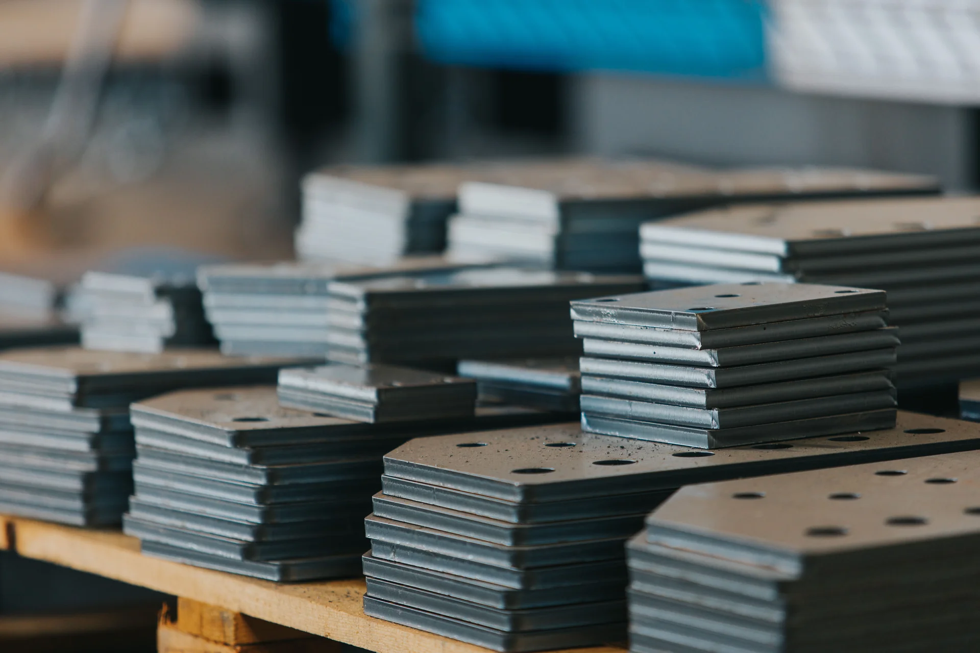
Stacked metal components with cut holes; industry illustration
01

Sheet Metal Fabrication

For panels, brackets, enclosures, machine parts and welded assemblies made from sheet metal. The typical route connects laser cutting, edge finishing, bending, welding, cleaning and marking. Selection depends on material grade, sheet format, thickness range, bend geometry, part mix and required output.

Structural steel assembly hall with overhead handling; industry reference
02

Steel Structures

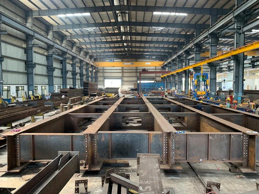
For plates, H-beams, I-beams, channels, tubes and other structural components. The central questions are workpiece size and weight, hole and notch geometry, joint preparation, material handling, part identification and fit-up before welding.

Open blue steel cabinet with adjustable shelves; product reference

Metal Furniture and Cabinets

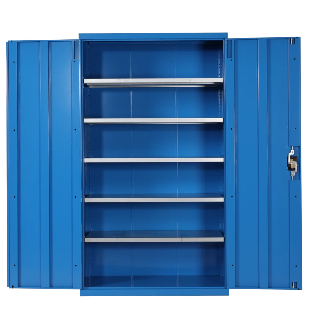
For cabinet bodies, doors, shelves, drawers, brackets, frames and visible metal parts. Repeatable cut dimensions, bend allowance, corner fit, weld distortion, safe edges and surface protection all affect the finished product.

Freestanding fabricated metal display lettering; reference

Signs and Displays

For metal lettering, sign cabinets, frames, brackets, display structures and compatible flexible or non-metallic graphics materials. The equipment route may combine metal fabrication with digital knife cutting, depending on the substrates in the job.

Open folded cardboard box; packaging reference

Packaging

For packaging prototypes, short runs and cut or creased components made from compatible board, foam and related sheet materials. Tool choice, crease behavior, print registration, hold-down and finished-package testing should be confirmed with actual material.

Collecting cut upholstery patterns from a digital cutting table; industry reference

Textiles and Upholstery

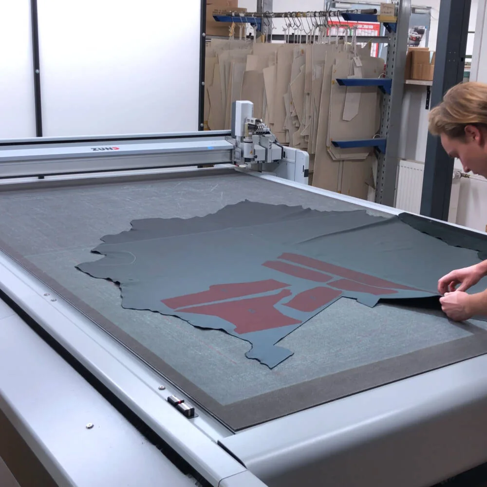
For patterns cut from compatible fabrics, leather or synthetic leather, felt, foam and other flexible materials. Material direction, stretch, porosity, surface variation, nesting and part collection are central to the cutting plan.

Match the Equipment to the Material and Workpiece

CHENDA’s documented range covers several distinct process families. They should be matched by workpiece form and operation:

CHENDA open sheet metal laser cutting machine
Production need Equipment direction Main information required
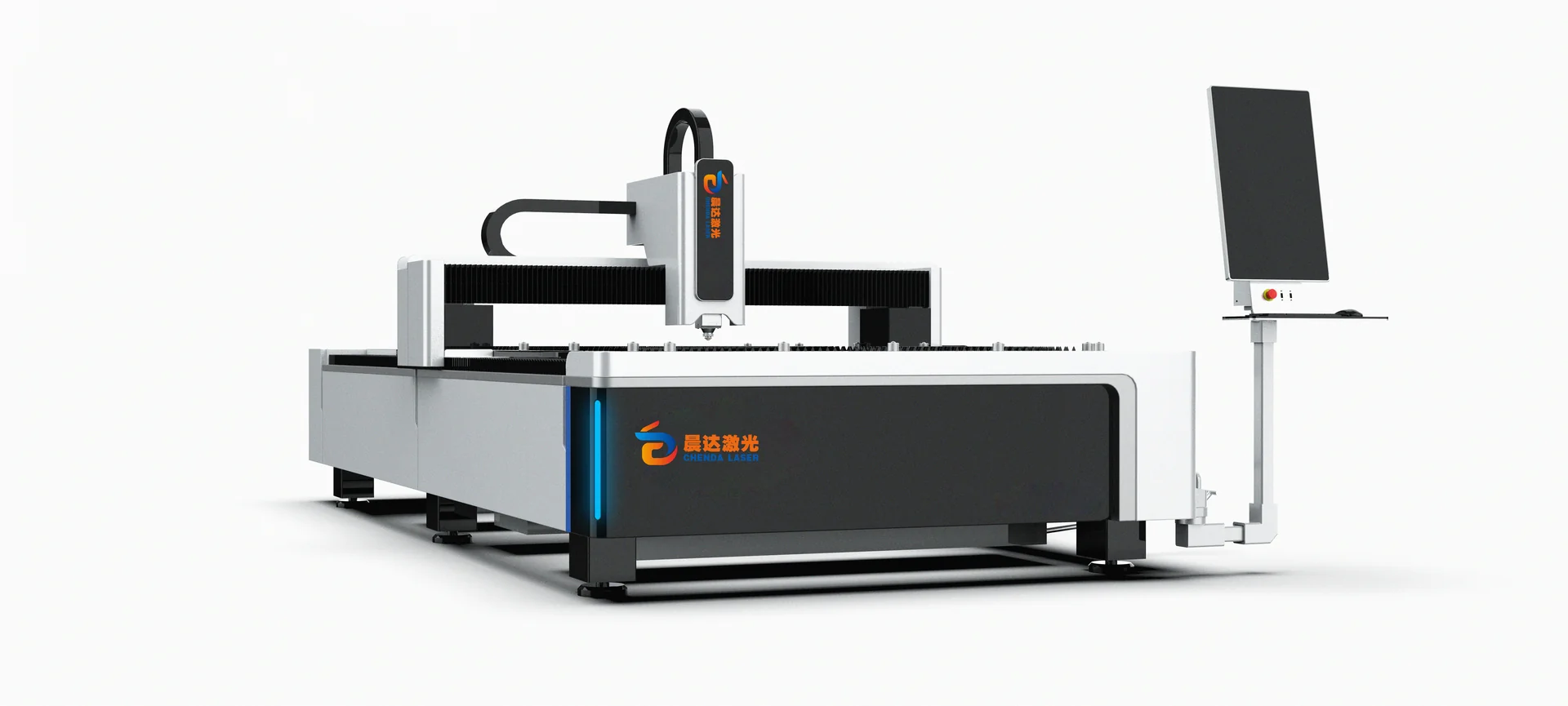
Cut flat metal sheet Sheet Metal Laser Cutting Machines Material, grade, thickness range, sheet size, part geometry and batch mix
Cut round, square or other supported tube and profile forms Tube Laser Cutting Machines or Profile Laser Cutting Machines Cross-section, size range, wall thickness, stock length, part length, holes, slots and end cuts
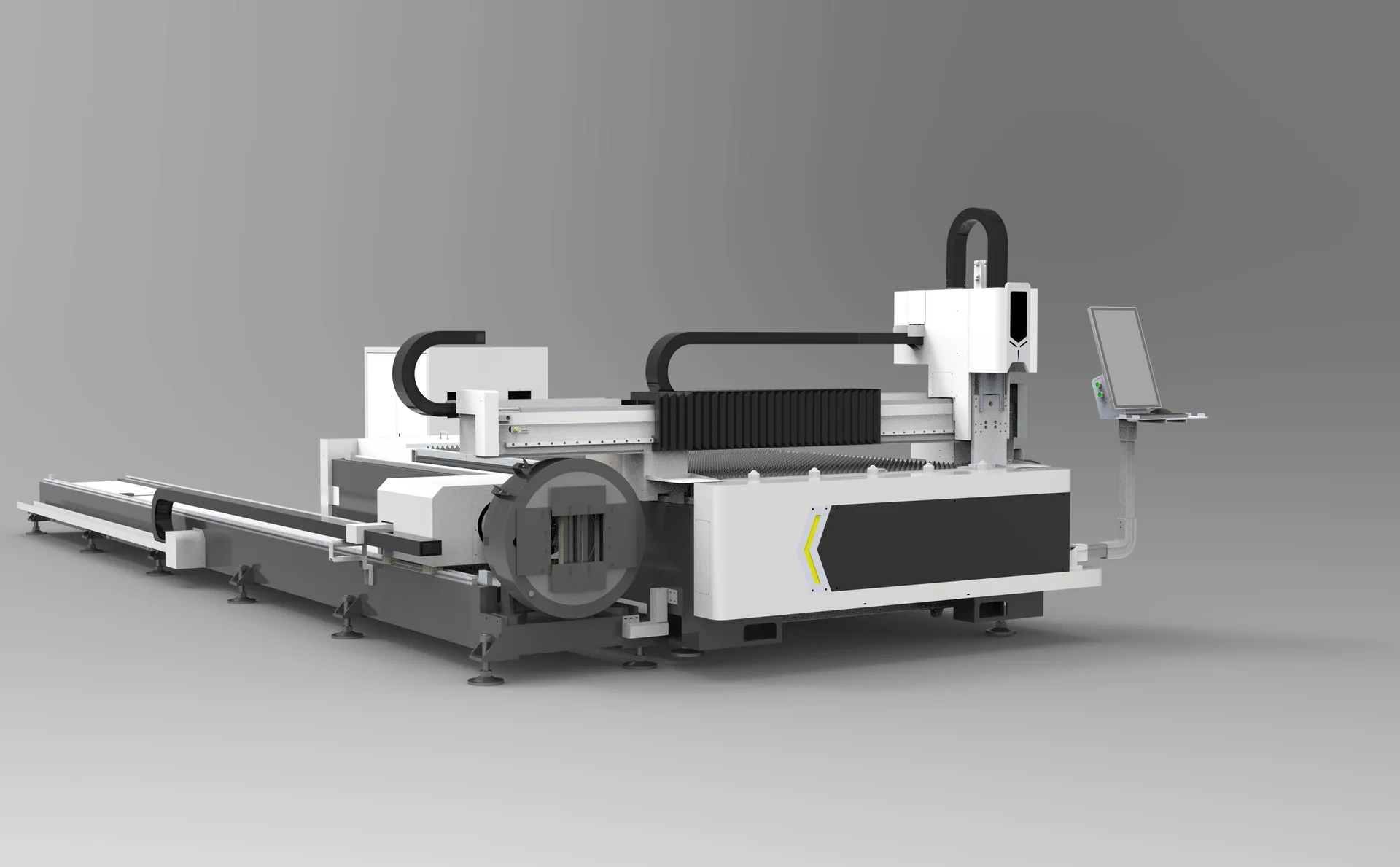
Cut sheet and tube with one equipment direction Sheet & Tube Laser Cutting Machines Workload split between sheet and tube, size range, loading method and changeover expectations
Form metal parts Press Brakes Material, thickness, bend length, bend angle, inside radius, flange depth, tooling and part weight
Join metal parts Welding Machines & Systems Base materials, joint design, penetration requirement, seam length, access, filler needs, fixture method and production repeatability
Remove selected surface contamination Laser Cleaning Machines Substrate, contaminant, coating or oxide condition, cleaning area, acceptable surface change and access
Add permanent identification Laser Marking Machines Material, mark content, mark size, contrast or depth requirement, cycle and traceability workflow
Improve cut edges or surfaces Deburring & Finishing Machines Burr type, edge target, part size, material, surface protection and downstream finish
Cut compatible flexible or non-metallic sheet materials Digital Knife Cutting Machines Material samples, thickness, roll or sheet format, tool action, printed registration, nesting and output
Provide compressed air where the selected process requires it Air Compressors Required pressure, flow, duty pattern, air quality and the connected equipment

Build the Process Chain Before Choosing a Machine

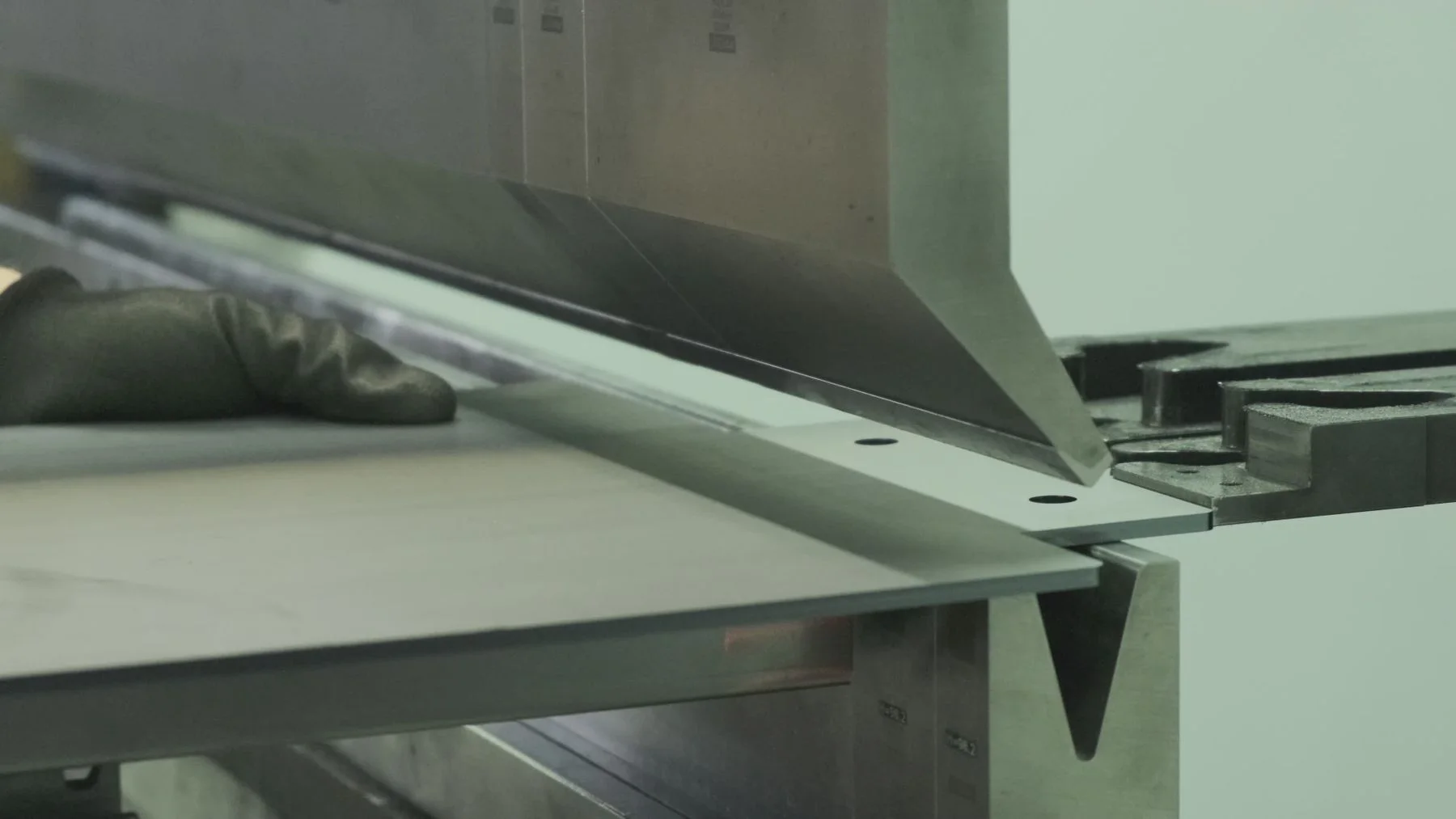
Sheet metal bending between a punch and V die; process reference
Metal fabrication

A useful equipment discussion follows the part through production. For a fabricated metal component, the route may begin with CAD data and nesting, continue through sheet or profile cutting, then move to deburring, bending, fit-up and welding. Cleaning or surface preparation may follow, while marking can support identification or assembly control. Final inspection should check the dimensions and features that matter to the next operation or the finished assembly.

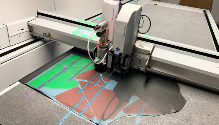
Digital cutting head above leather with projected pattern outlines; process reference
Flexible materials

For packaging or textile work, the route is different. It starts with artwork or pattern preparation, material inspection and nesting. Loading and hold-down must keep the material stable without damaging it. The selected tool then cuts, creases, perforates or performs another verified operation. Parts are removed, sorted and tested in the real assembly, folding, sewing or upholstery step.

Mapping the full route reveals hidden constraints. A fast cutting process has limited value if parts are difficult to sort, bends cannot be made with available tooling, weld joints are inconsistent, or flexible materials shift before the tool reaches them.

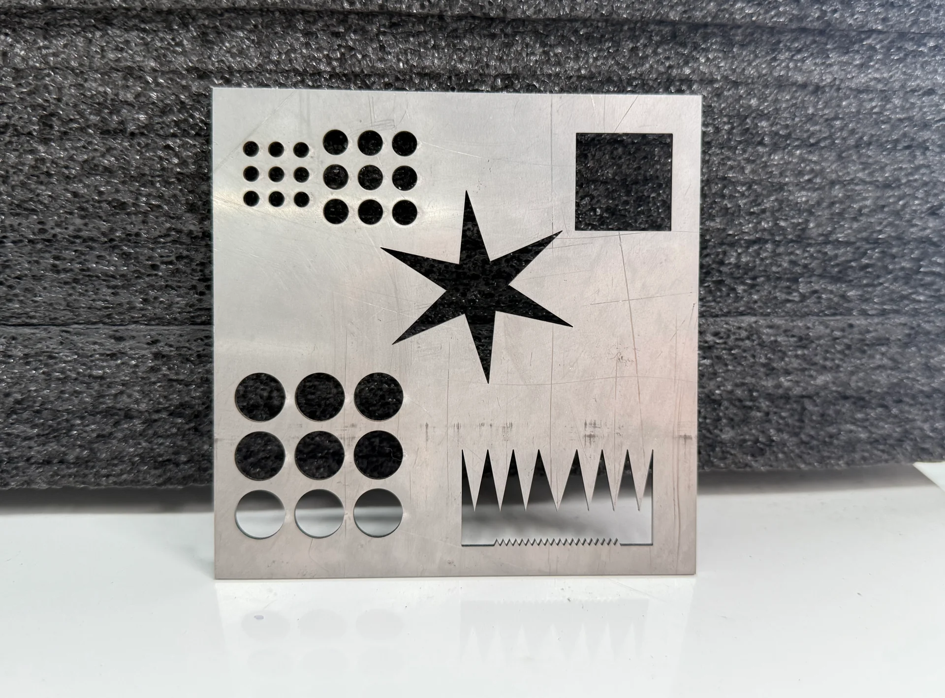
Metal test piece with cut holes, slots and geometric features

Quality Risks to Define Early

Do not use “good quality” as the acceptance standard. Define what can be measured or observed on a representative part.

  • Cut parts: dimensional error, taper, dross, burr, heat effect, incomplete features, scratched surfaces or unstable small details.
  • Bent parts: incorrect angle, flange dimension, inside radius, springback, tool marks, collision risk or variation caused by material properties.
  • Welded assemblies: poor fit-up, inconsistent seam position, insufficient or excessive penetration, porosity, undercut, spatter, distortion or difficult access.
  • Cleaned or marked surfaces: substrate change, incomplete contaminant removal, uneven appearance, poor contrast, unreadable codes or a mark that does not meet the required durability.
  • Deburred parts: remaining sharp edges, excessive rounding, directional finish differences or damage to coated or visible surfaces.
  • Knife-cut materials: drag, tearing, fraying, crushed structure, incomplete cutting, poor crease response, print-to-cut error, material movement or distorted patterns.

The acceptable result depends on the material and end use. Sample testing should reproduce the intended material, geometry and process as closely as possible.

Information to Send for Equipment Selection

A clear inquiry shortens the path to a useful recommendation. Include:

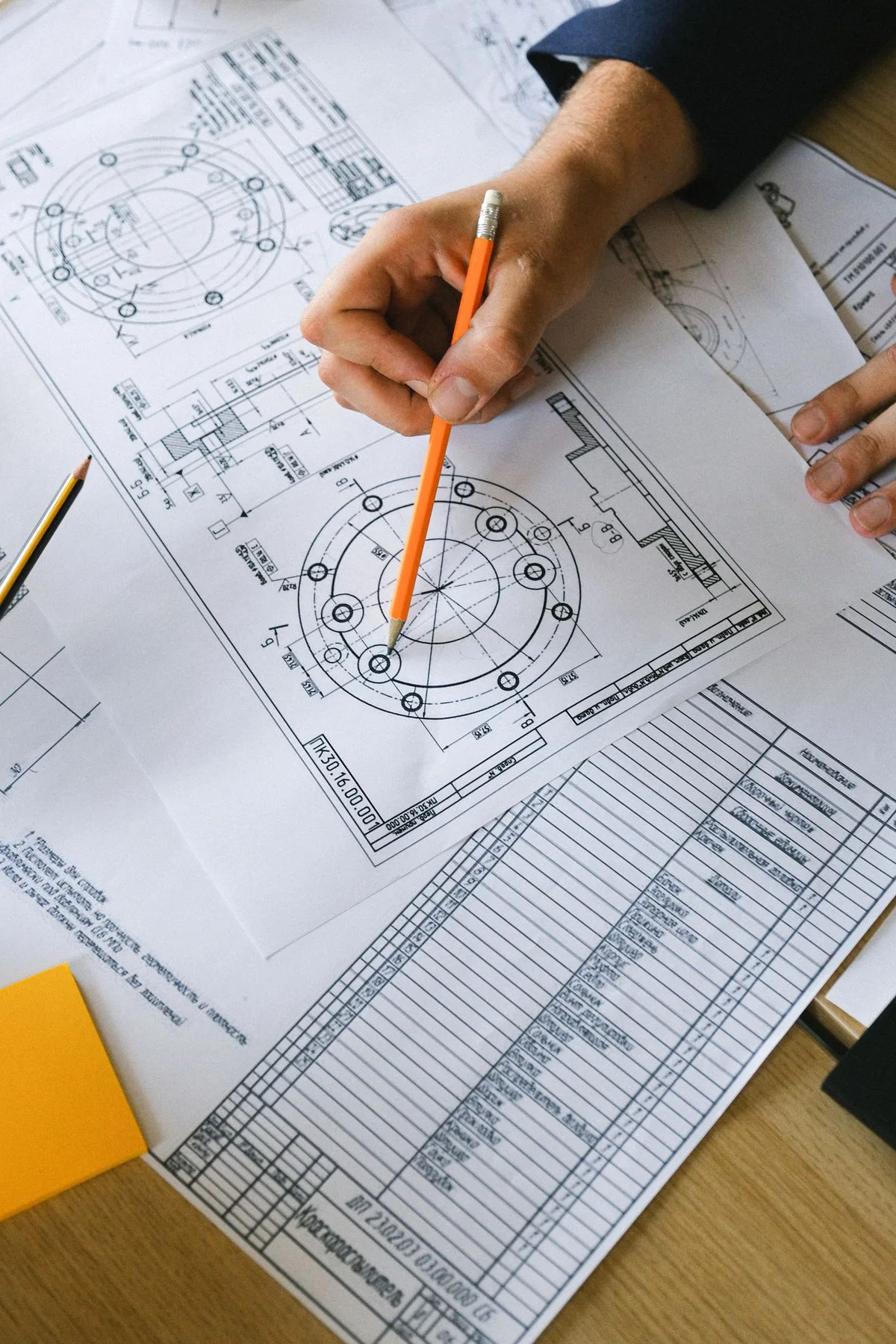
Mechanical component drawings with dimensional callouts; reference
Representative drawings help define the workpiece · reference
  1. Material names, grades and representative samples where practical.
  2. Minimum, typical and maximum thickness or profile dimensions.
  3. Sheet, tube, profile, roll or pattern sizes.
  4. Drawings in an available production format, plus photos of the finished part.
  5. Typical batch size, product mix, working hours and the expected production rhythm.
  6. Required cut, bend, weld, clean, mark, finish, crease or registration result.
  7. Current upstream and downstream operations.
  8. Loading, unloading, lifting and factory-space constraints.
  9. Available electrical supply, extraction and compressed-air conditions.
  10. The acceptance features that will decide whether the equipment is suitable.

Questions for a Meaningful Acceptance Plan

Before agreeing on a configuration, ask how the proposed equipment will be checked:

  • Which customer drawing and material will be used for the sample or acceptance part?
  • What dimensions, edge conditions, bend results, weld features or cut patterns will be evaluated?
  • How will repeatability be checked across more than one part or production cycle?
  • Which tooling, assist gas, fixtures, extraction, software or consumables are included in the demonstrated process?
  • What operator actions are required for loading, setup, changeover, part sorting and routine maintenance?
  • Which workshop utilities and environmental conditions must be ready before installation?
  • What documentation, training and support scope applies to the proposed order?
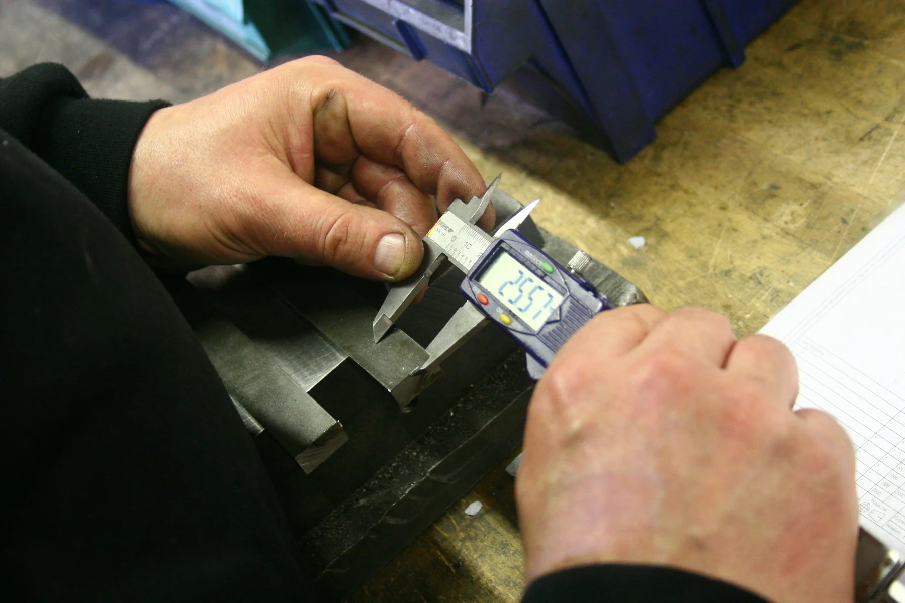
Measuring a metal component with a digital caliper; industry reference
Measurement of a metal component · industry reference

Frequently Asked Questions

Combined sheet and tube laser cutting equipment

Can one machine cover every material used in our factory?

Usually not. Metal laser cutting and digital knife cutting use different process principles, and even within one category the workpiece form matters. Start by separating sheet metal, tube or profile, and flexible or non-metallic materials. Then define which operations and material ranges must share one system.

Should we choose equipment by the largest part we ever make?

The occasional maximum part matters, but it should be considered alongside the normal workload. A useful selection compares typical production, peak requirements and future products so that exceptional jobs do not distort the whole investment.

When is automation worth considering?

Automation becomes more relevant when parts, loading conditions and process timing are repeatable. High product variation, unstable fixtures or poorly controlled incoming material can limit the benefit. Review the complete flow, including loading, unloading, sorting and changeover.

Do you need samples as well as drawings?

For many applications, yes. Drawings define geometry, but samples reveal surface condition, flatness, coatings, stretch, porosity, grain, construction and other behavior that can affect the process.

Cut metal profiles and plate edges showing different workpiece forms

Continue Your Equipment Review

Browse all Products, review available Resources, or learn how application discussion, installation and training fit into Support. For a specific project, contact CHENDA or request an equipment quote with your drawings, materials and acceptance priorities.