CHENDA · Steel fabrication

Laser Cutting and Welding Equipment for Steel Structures

Steel-structure fabrication combines heavy material handling with accurate holes, notches, copes, bevels and joint preparation. The correct equipment route depends on whether the work begins as plate, tube, beam, channel or another supported section. Section size, length and weight can drive the machine layout before laser power is considered.

Explore equipment by workpiece
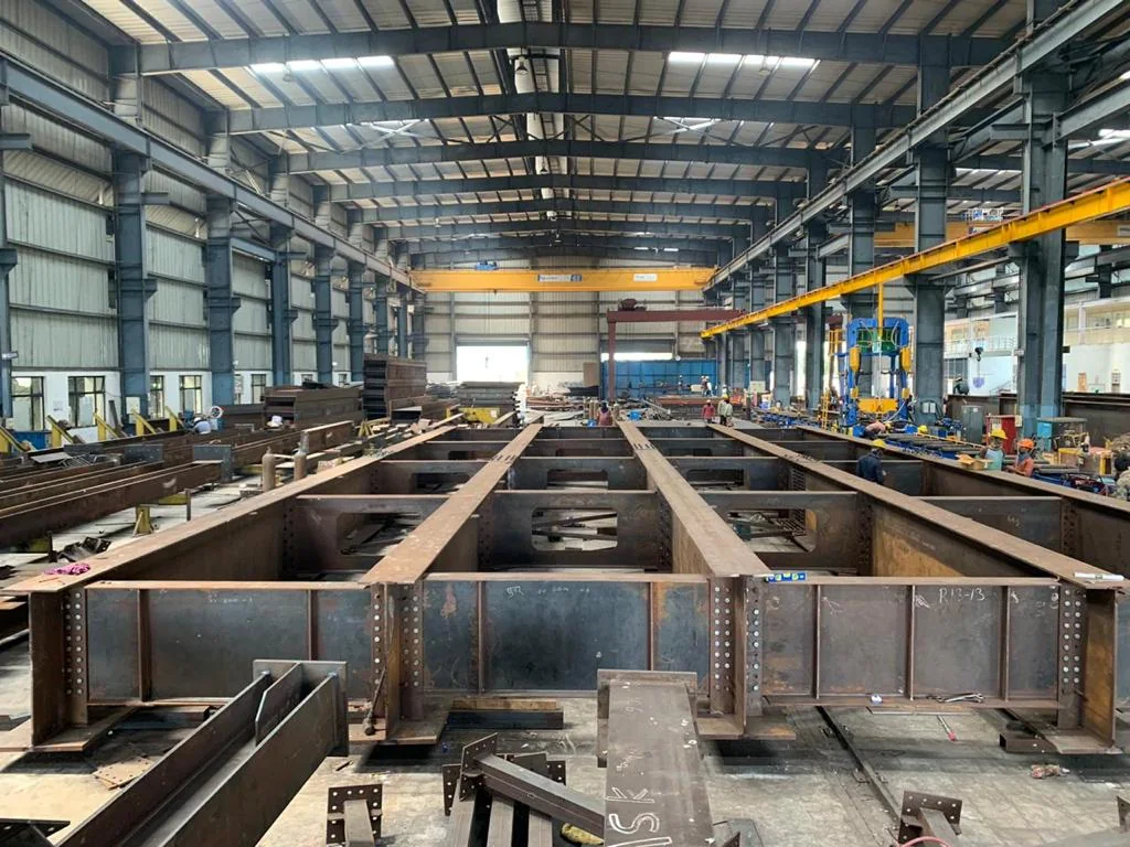
Steel beams and structural assemblies beneath overhead cranes in a fabrication hall; industry reference
Structural steel fabrication · industry reference

CHENDA’s documented range includes large-format plate cutting, heavy tube cutting and a dedicated structural-profile direction for supported H-beam, I-beam, channel and plate work. The catalogue describes combined cutting, hole making, notching and optional joint-preparation functions on relevant configurations. These capabilities must be confirmed against the exact section, drawing and machine proposed for the project.

01 / Three starting points

Workpiece Families Require Different Machines

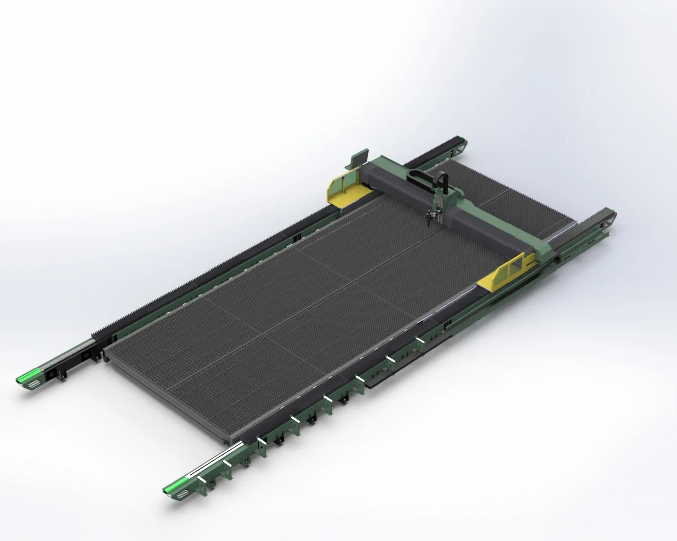
Large-format ground-rail plate laser cutting machine, equipment illustration
Large-format plate cutting · equipment illustration
01 / FLAT STOCK

Plate

Base plates, gussets, stiffeners, brackets, connection plates and long structural components may use sheet and plate laser cutting. Large-format ground-rail systems become relevant when normal plates exceed standard sheet formats or when thick, heavy plate handling dominates the workflow.

Confirm plate length, width, thickness, unit weight, flatness and loading method. A large cutting envelope is useful only when storage, cranes, nesting, extraction, slag handling and finished-part removal can support it.
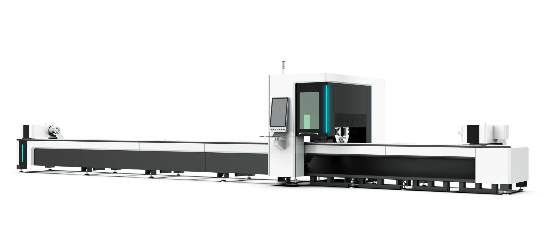
Long-bed tube laser cutting machine, equipment illustration
Long-bed tube cutting · equipment illustration
02 / CLOSED SECTIONS

Tube and hollow section

Round, square and rectangular hollow sections can use tube laser cutting machines. Selection should consider chuck range, stock length, unit and per-meter weight, support positions, sag, straightness, seam orientation, unloading length and remnant target.

Heavy or long stock may require side loading, additional supports, a three-chuck arrangement or a dedicated unloading design. “Zero tail” or short-remnant claims should be checked on the actual geometry and clamping sequence.

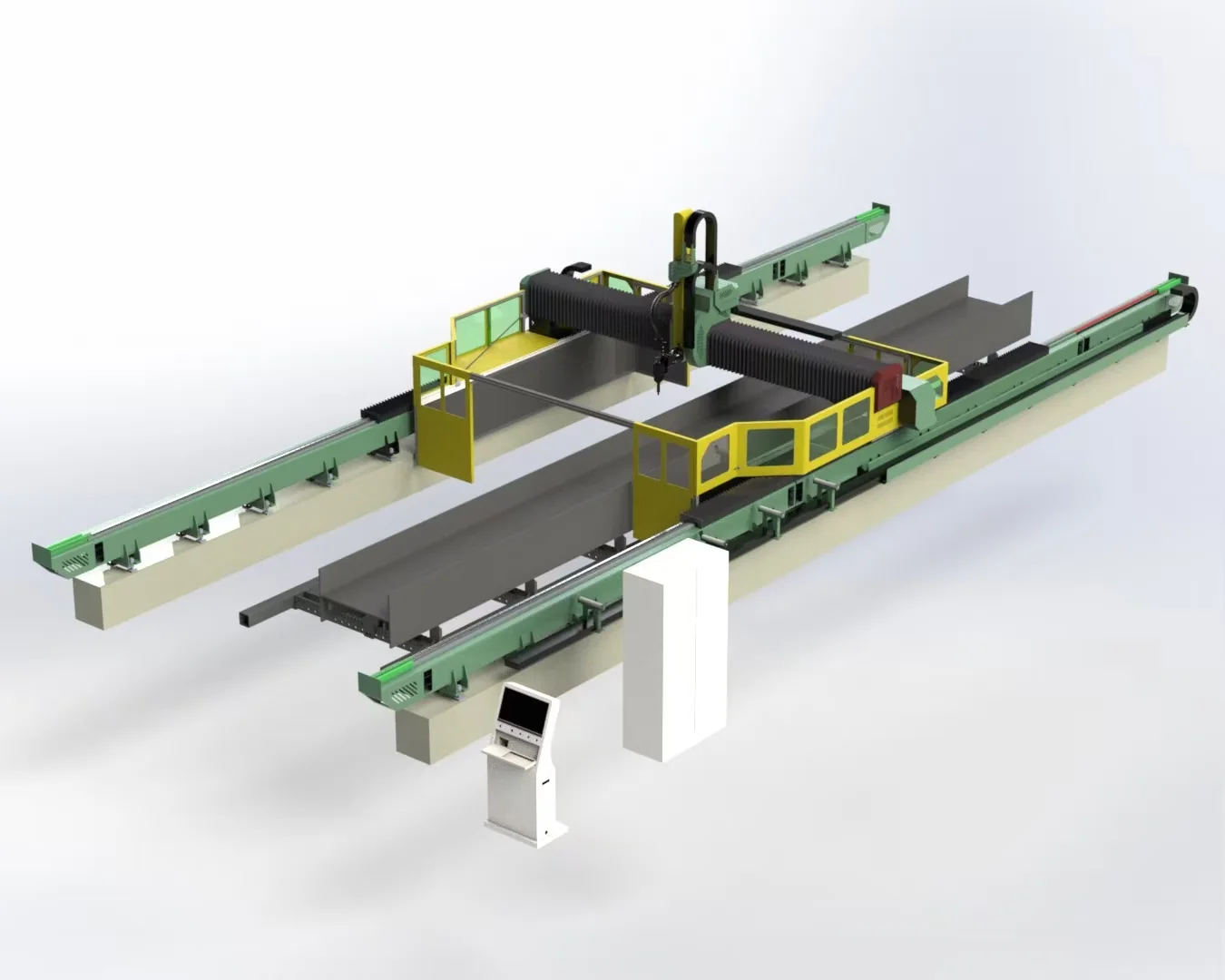
Gantry laser system around a structural steel section, equipment illustration
Structural-profile cutting · equipment illustration
03 / OPEN SECTIONS

Beams, channels and open profiles

Use a profile laser cutting direction when the machine and software are designed for the required structural sections. Open profiles behave differently from round tube. The system must manage section variation, flange and web access, clamping or support, datum detection and possible interference.

Send section standards, flange and web dimensions, length, mass, camber or twist limits and the exact features required on each face.

02 / Evaluate the complete route

Replace Process Steps Only After Mapping Them

Traditional structural preparation may use sawing, drilling, coping, punching, marking and grinding as separate operations. A dedicated laser system may combine several programmable features, but the business case depends on the real part mix and downstream fit-up.

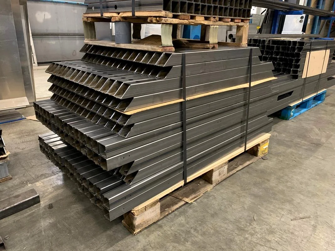
Cut rectangular steel profiles with connection holes stacked on pallets; industry reference
Cut profiles prepared for handling · industry reference

Map the current route:

  1. Material receipt and storage
  2. Stock identification and length control
  3. Sawing or primary cutting
  4. Holes, slots and connection features
  5. Notches, copes and end profiles
  6. Bevel or weld preparation
  7. Part marking and sorting
  8. Fit-up, tack welding and final welding
  9. Inspection, coating preparation and dispatch

Then identify which steps the proposed machine will remove, combine or leave unchanged. Include programming, loading, unloading, remnant handling and rework in the comparison.

03 / Before the weld

Joint Preparation and Fit-Up

Structural weld quality begins before the welding station. Hole location, end cut, bevel angle, root face, member length and datum control affect assembly. If the proposed laser configuration includes bevel cutting, confirm:

  • Supported material and section
  • Bevel type and accessible faces
  • Angle and geometry range
  • Effective thickness and edge result
  • Collision and clamping limits
  • How the machine locates a real, imperfect section
  • Inspection method after cutting

Do not treat “bevel option” as proof that every joint in the drawing can be produced in one setup.

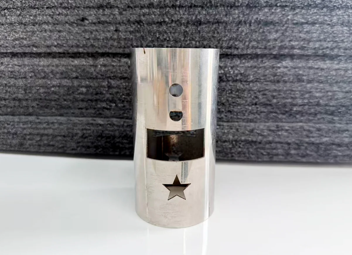
Tube sample with holes and cutout profiles
Cut features on a tube sample · geometry illustration
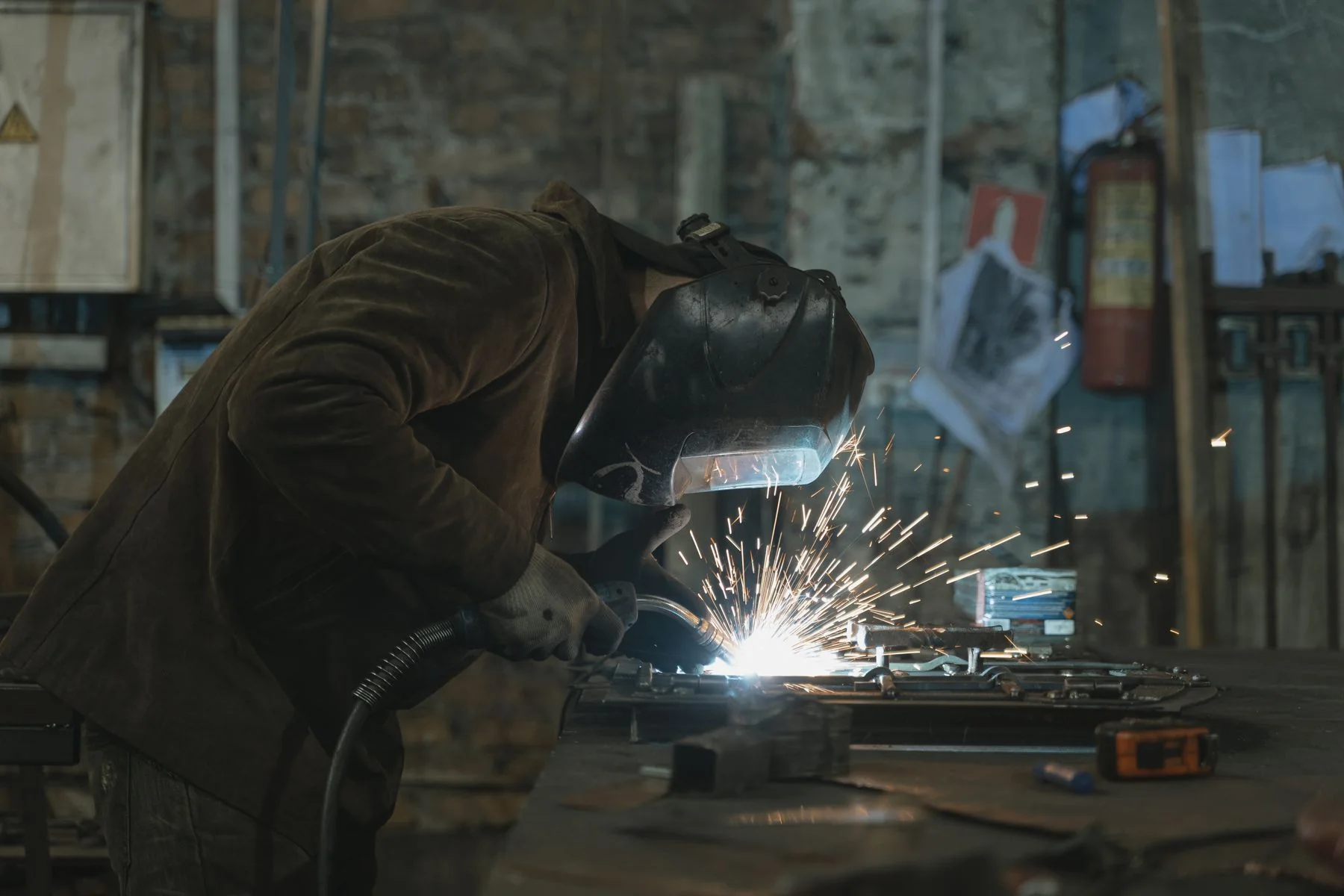
Welder assembling metal components with an arc welding torch; industry illustration
Arc welding · industry process illustration

04 / Joining and fit-up

Welding Route

Structural fabrication may use arc welding, laser welding or a combination depending on section, joint, gap, penetration, code and production method. CHENDA’s project library includes a portable collaborative robotic MIG/MAG solution using a separate welding power source, and it also includes collaborative laser-welding systems. These are not variants of the same process.

Robotic MIG/MAG welding can suit repetitive arc-welded joints when fixtures, access and procedure are controlled. Robotic laser welding can provide concentrated heat input on suitable joints but generally demands consistent fit-up and laser-specific safety controls.

Send weld symbols, base materials, joint details, gap range, position, filler, gas, penetration and any applicable code or procedure qualification. Equipment selection does not replace welding engineering or required qualification.

05 / Plan the entire cell

Material Handling Determines Real Output

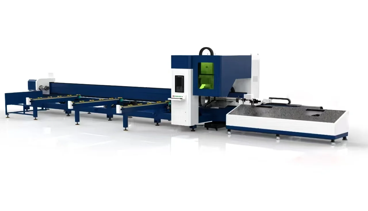
Tube laser cutting line with long stock supports, equipment illustration
Tube cutting line and stock supports · configuration illustration

Long and heavy stock needs a material-flow plan. Consider:

  • Truck or yard to storage
  • Storage to machine loading zone
  • Crane, forklift, roller, rack or bundle loader
  • Safe orientation and separation of profiles
  • Support during cutting and after separation
  • Removal of hot parts, slag and remnants
  • Part labeling and routing to fit-up bays
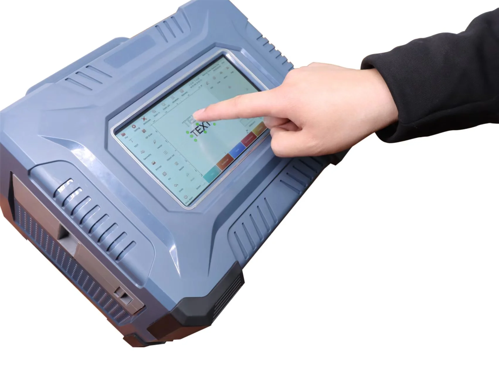
Operator editing text on a portable laser marking machine interface
Laser marking interface · equipment detail

06 / Keep the part identifiable

Part Identification and Assembly Control

Structural projects often contain similar members with small feature differences. A marking function can support part names, assembly positions or references on compatible surfaces, but the mark must remain readable after handling and any shot blasting, cleaning, coating or welding.

Confirm mark content, position, depth or contrast and downstream survival. Maintain a link between the production file, material heat or batch information where required, and final assembly identification. Laser marking equipment may support separate traceability tasks when integrated marking on the cutting system is not suitable.

07 / Build the section schedule

Information Required for Selection

Review of dimensions on mechanical drawings; industry illustration
Drawing review · industry illustration

Provide a schedule that covers the production range:

  • Section names and standards
  • Minimum, typical and maximum cross-sections
  • Wall, flange, web or plate thicknesses
  • Stock lengths and unit weights
  • Representative 3D models and drawings
  • Features on each face
  • Bevel and weld-preparation details
  • Finished-member tolerance and datum method
  • Batch sizes, repetitions and project mix
  • Desired remnants and material-utilization method
  • Loading and unloading resources
  • Downstream fit-up and welding process

08 / Verify the real member

Acceptance Plan for Structural Work

Choose a member that represents the real section, length, weight and feature access. The test should cover critical holes or slots, end geometry, notches, bevels and marking. Measure feature location from the assembly datums used in production, not only from a convenient cut edge.

For long members, check accumulated length and alignment. For open profiles, record flange and web variation. If loading or support is part of the investment case, include it in the witnessed cycle. A short offcut can validate local geometry but may not validate long-stock support or material flow.

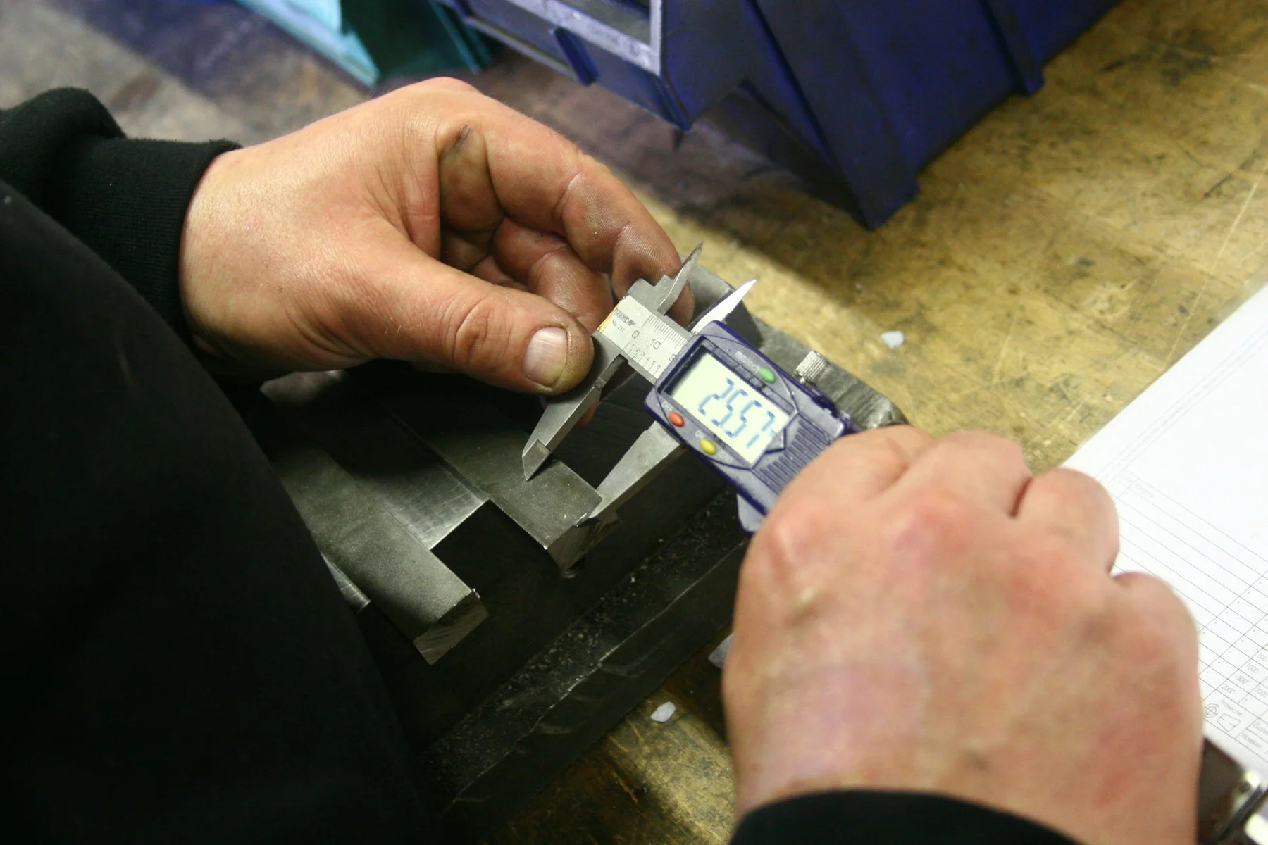
Digital caliper checking a metal component; measurement illustration
Part measurement · industry illustration

09 / Test the constraints

Common Risks

Cut rectangular steel profiles with connection holes stacked on pallets; industry reference
Profile geometry and length · industry reference
  • Section tolerances or twist shift the detected surface
  • Heavy stock exceeds chuck, support or loading limits
  • Long members sag and change cut position
  • Clamps interfere with end features or increase remnant
  • Heat and cutting sequence affect narrow features
  • Bevel geometry does not match the actual joint design
  • Parts lose identity between cutting and fit-up
  • Robot reach is adequate, but the torch cannot access the joint orientation
  • Fixture or incoming fit-up variation prevents repeatable welding

Address these risks in drawings, sample testing and the acceptance checklist.

10 / Selection questions

Frequently Asked Questions

Gantry laser system around a structural steel section, equipment illustration
Profile cutting system · configuration illustration

Can one profile machine process beams, channels and tubes?

Only if the specific machine, support, clamping, software and cutting head are designed for those forms and sizes. Send the complete section schedule and require written confirmation.

Is laser cutting always better than drilling and sawing?

It can combine programmable features and reduce transfers, but economics depend on the part mix, thickness, edge requirement, loading and downstream needs. Compare the full route and not only one operation.

Can the machine mark welding positions?

Relevant profile systems may support marking functions, but the exact mark, accuracy, visibility and effect on the material must be confirmed. Treat it as an acceptance item if assembly relies on it.

What matters most in robotic structural welding?

Repeatable part datum, joint access, fixture strength, gap control, welding procedure, cable management and a safe cell. Payload and reach are necessary inputs but do not establish process feasibility.

Discuss your structural workflow

Define the Section Schedule First

Explore laser cutting equipment, welding systems and CHENDA’s quality-control approach.

Large-format ground-rail plate laser cutting machine, equipment illustration
Start with the section, length, weight and features.