Digital Cutting Equipment for Packaging Samples and Short Runs
Digital knife cutting converts CAD files into packaging samples, inserts and short-run components without a physical cutting die. It is useful when designs change frequently, quantities are limited or a team needs to test structure before committing to production tooling. The correct system depends on the actual board, foam or sheet material, not the word “packaging.”
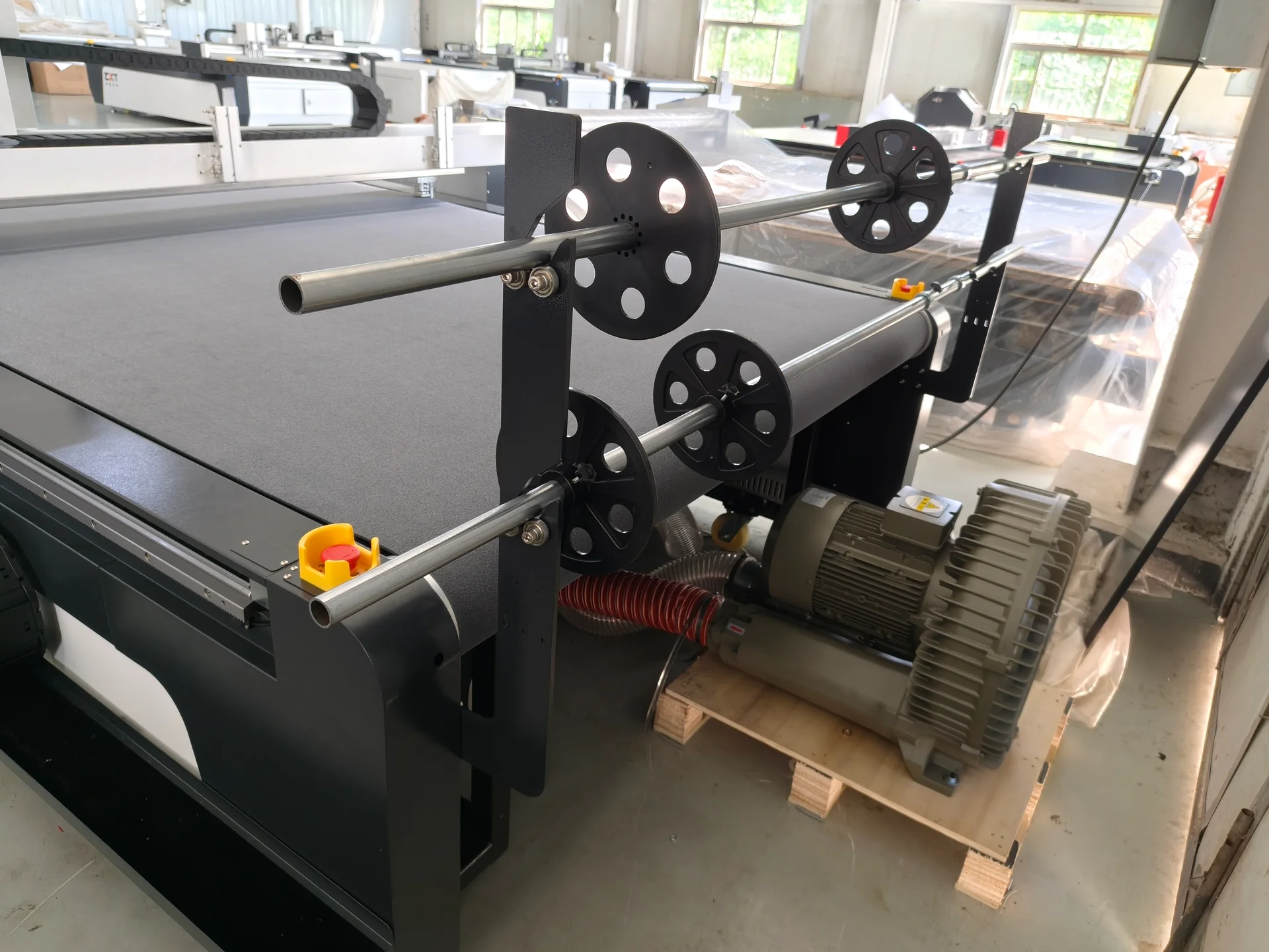
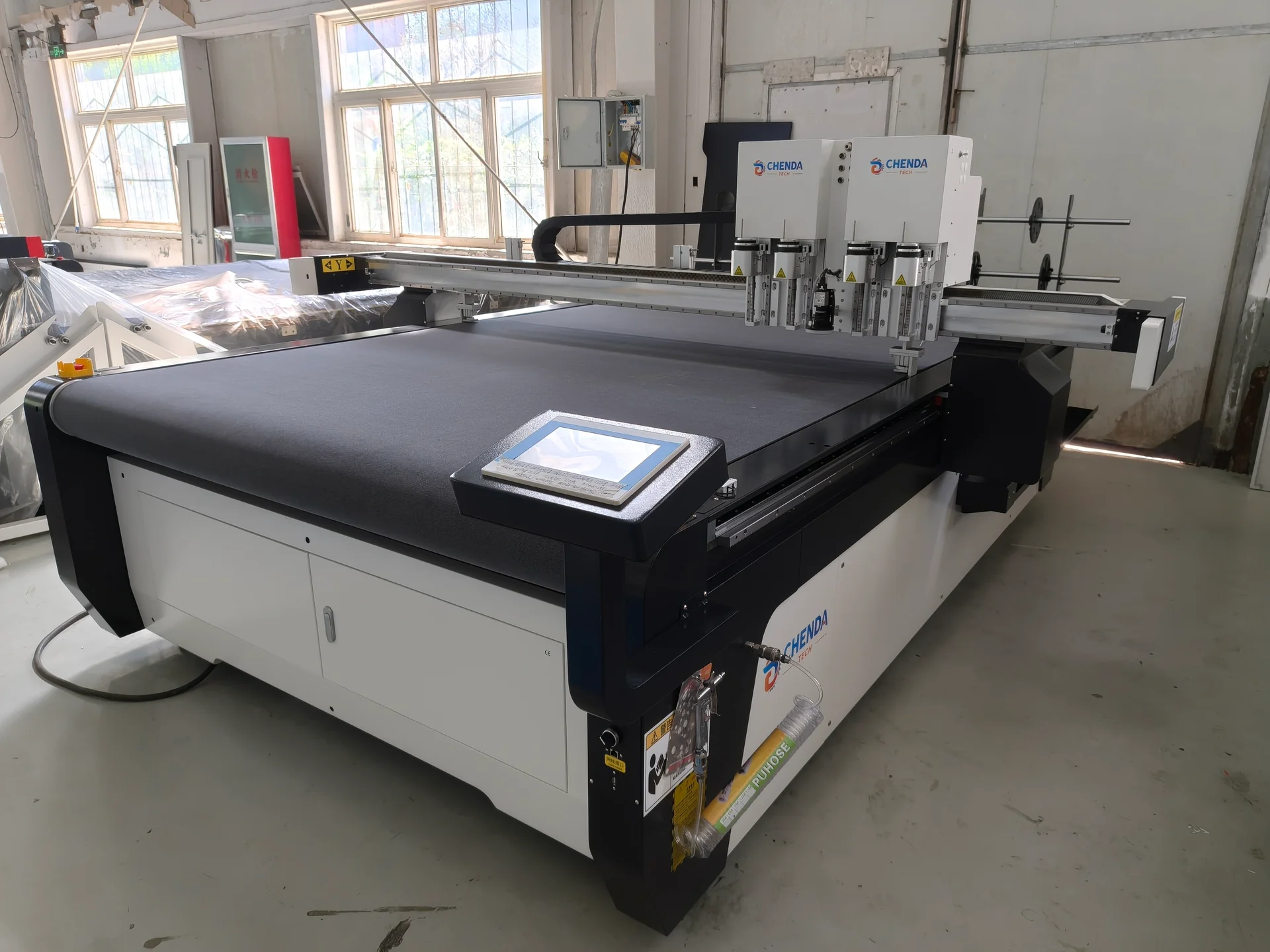
CHENDA’s local project library includes a flatbed digital knife cutting machine and related operating video. A proposal should confirm the working area, hold-down method, tools, supported material and feeding configuration for the buyer’s samples. This page does not claim that every packaging substrate has already been validated.
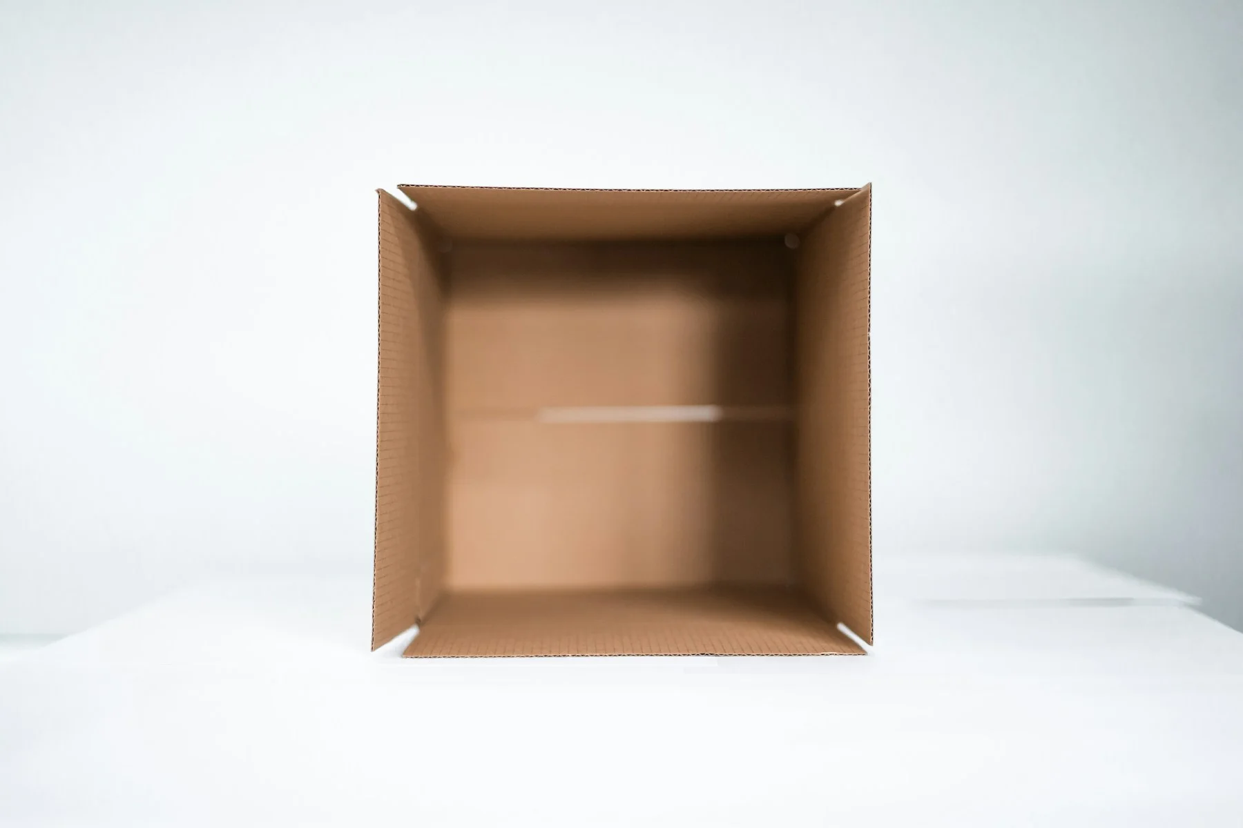
Start with the package structure · application illustrationFrom the flat sheet to the fold
01 / Samples, inserts and short runs
Packaging Jobs to Evaluate
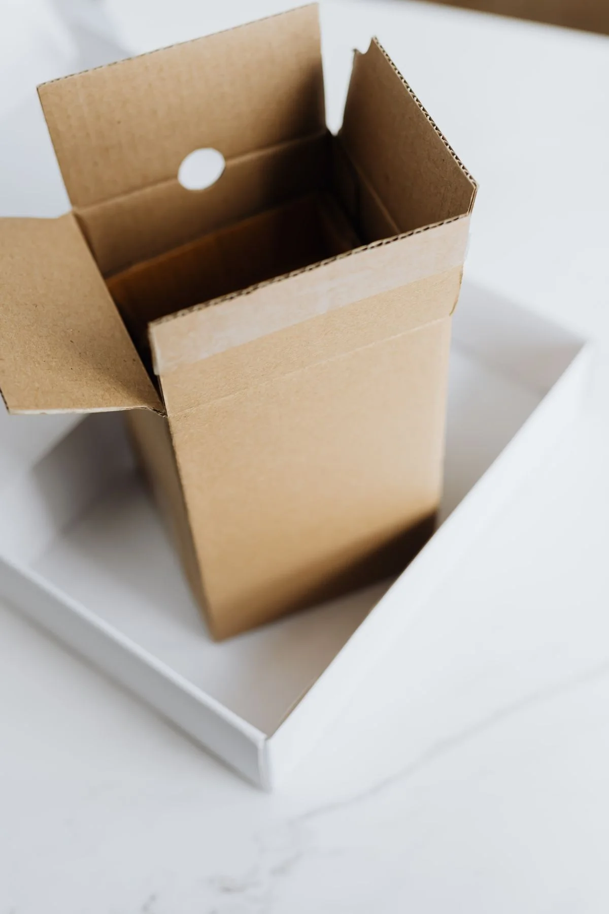
Folding-carton and corrugated prototypes
Protective foam inserts
Display and point-of-sale structures
Gaskets, liners and separators made from compatible sheet material
Short-run customized packs
Design validation and preproduction samples
Printed packaging that requires contour registration
Each job can require a different combination of through cutting, creasing, perforating, kiss cutting, V-cutting or marking. The quoted tool set should identify which operation is proposed for each material.
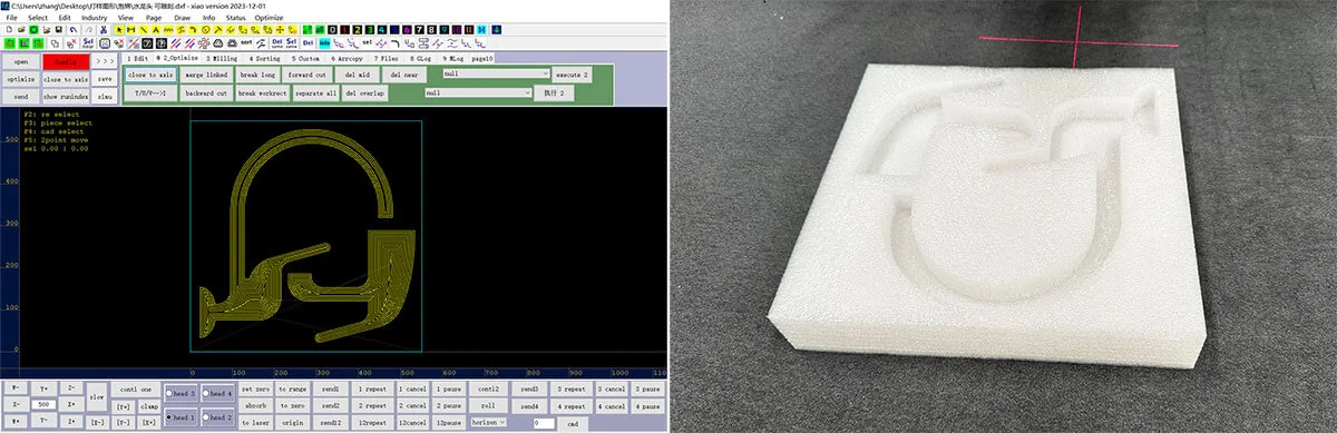
Cut foam packaging geometry · process reference
02 / Define the construction
Material Definition Comes First
Packaging names are often incomplete. “Corrugated board” does not identify flute, liner, total thickness, warp or recycled content. “Foam” may refer to several polymers, densities and cell structures. Laminated boards can combine paper, film, foil, adhesive and a core.
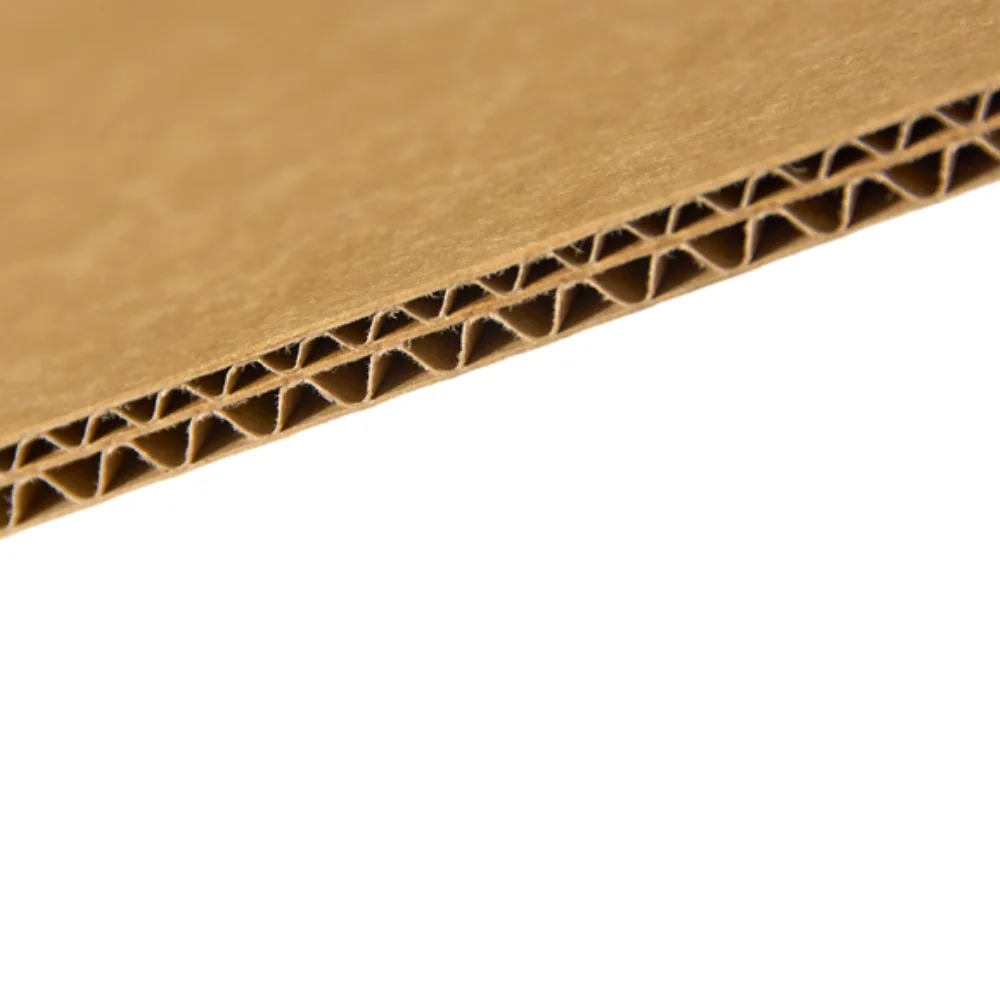
Corrugated core and liner layers · material reference
For each material, provide:
Manufacturer and trade name
Composition and safety data where relevant
Total thickness and layer construction
Sheet or roll size
Density, flute or core structure
Surface coating, print, laminate and adhesive
Grain or flute direction
Normal flatness, warp and storage condition
Required finished edge and allowable compression
Send representative samples from normal production. A small pristine sample may behave differently from a full warped sheet stored in the workshop.
03 / The path from file to fit
Digital Workflow From CAD to Package
01 / FILE
Structural design
The CAD file should contain cut, crease, perforation and other operations on clearly identified layers. Confirm units, scale, crease allowance and material direction. Maintain revision control so the operator can connect the job file to the approved sample.
02 / LAYOUT
Nesting and layout
Nesting should respect print orientation, grain, flute, surface defects and tool access. Material utilization matters, but a layout that makes part removal or kit sorting unreliable can increase total cost.
Digital geometry and a cut sample · process reference
03 / STABILITY
Loading and hold-down
The material must remain flat and stable. Vacuum performance depends on porosity, leakage around the sheet, zone control and cut openings. Dense board, porous corrugated and open-cell foam behave differently. Roll material adds tension, tracking and feed requirements.
04 / CUTTING
Toolpath and process
The controller follows the selected operations. Toolpath order can affect material stability after internal cutouts release. Corners, small holes and narrow bridges may require a different speed or blade from long straight cuts.
05 / ASSEMBLY
Removal and assembly
Operators remove parts, strip waste, separate kits and fold or assemble the sample. This stage reveals crushed flutes, torn liners, weak creases, inaccurate tabs and interference that may not be obvious on a flat part.
04 / Select the action
Tool Choice Affects the Finished Package
The exact tools available depend on the machine configuration. Evaluate tool actions by result:
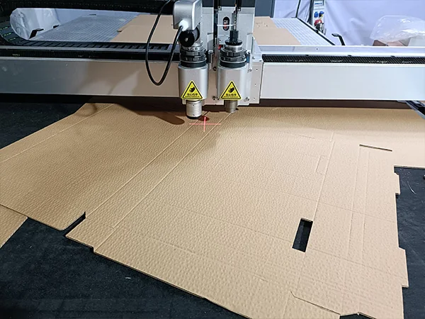
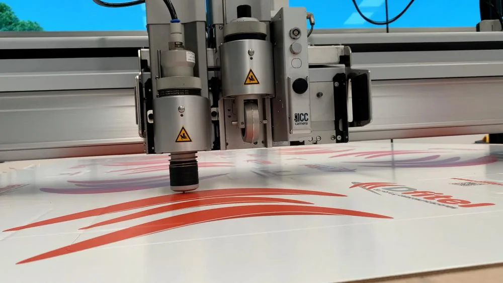
Cutting and crease tooling over a carton blank · process reference
Through cutting: the blade must separate all layers without excessive overcut or table damage.
Creasing: wheel shape, force and direction should create a controlled fold without cracking the print or crushing the structure beyond the design intent.
Kiss cutting: depth must separate the top material while preserving the liner.
Oscillating cutting: powered blade motion can help selected thicker or tougher materials, subject to validation.
V-cutting: angled cuts can support folded structures in suitable material but require correct geometry and tool configuration.
Perforation: cut and bridge length should match tear behavior and structural strength.
Do not request every tool by default. Specify the packaging operations and test the proposed set.
05 / Align the artwork
Printed Packaging and Registration
Print-to-cut work requires a reliable relationship between artwork and the physical sheet. A camera or registration system can locate marks, but it cannot correct every source of distortion.
Check:
Print scale in both axes
Rotation and skew
Sheet expansion, contraction or warp
Lamination shift
Registration-mark size, contrast and placement
Lighting and surface reflection
Whether each sheet needs individual correction
Acceptable contour-to-print error on the finished package
Use a production print, not an unprinted substitute, for acceptance.
Camera and tooling over a production print · industry reference
Folded board structures · packaging illustration
06 / Compare the whole job
Digital Cutting Versus a Physical Die
Digital cutting avoids die manufacture and supports immediate file changes. It is strong for prototypes, variable designs and short runs. A physical die may offer lower cycle time at stable high volume. The crossover depends on die cost, setup, run length, material, number of variants, labor and required turnaround.
Compare cost per approved package, not only machine cutting time. Include file preparation, loading, cutting, removal, assembly, waste, blade use and rework.
07 / Build the application brief
Production Questions That Determine the Configuration
CHENDA flatbed digital knife cutter
What is the largest sheet or pattern?
Will material arrive in sheets or rolls?
Which materials account for most hours?
Which jobs require print registration?
Which operations need separate tools?
What is the smallest detail and shortest crease?
How many designs change each day or week?
How will parts and kits be collected?
Is the system for a design room, sample department or production floor?
What dust, waste and material-safety controls are required?
Select a real package that includes outside cutting, internal features, tabs, slots, creases and any printed registration. Use the intended material and printing or lamination. If the system must cover several material families, test one representative job from each family.
Inspect:
Dimensions and repeatability
Registration to print
Cut completion on both faces
Liner or surface tearing
Flute or foam compression
Corner overcut and small-feature quality
Crease position and fold behavior
Tab insertion and finished assembly
Loading, tool change, part removal and total cycle
Retain the accepted sample and record the file, material and tool settings. It becomes a practical reference for commissioning.
09 / Read the defect
Common Problems
Flute and liner structure · material reference
Board moves during cutting: insufficient hold-down, warped stock, wrong zone setup or toolpath sequence
Printed contour shifts: print distortion, registration setup, laminate movement or calibration
Crease cracks: material coating, grain direction, crease tool or force does not match the structure
Foam edge tears: blade, oscillation, speed, density or material support is unsuitable
Output falls below expectation: loading, waste stripping, kit sorting or frequent tool changes dominate the cycle
10 / Digital cutting questions
Frequently Asked Questions
Foam insert geometry · application reference
Can a digital cutter replace every packaging die?
No. It can remove die requirements for many prototypes and short runs, while stable high-volume jobs may still favor dedicated tooling. Compare the complete cost and delivery requirement.
Do you need our material before quoting?
Basic dimensions can frame a proposal, but actual samples are important for tool selection and reliable acceptance. Provide material data and enough sheets for repeated tests.
Can one tool cut board, foam and film?
Usually different materials and operations require different blades or tools. The configuration should map each material to a proposed action.
What proves the machine can cut our packaging?
A documented sample using your material, file, print and acceptance checks provides stronger evidence than a general video. Repeat the critical features more than once when consistency matters.