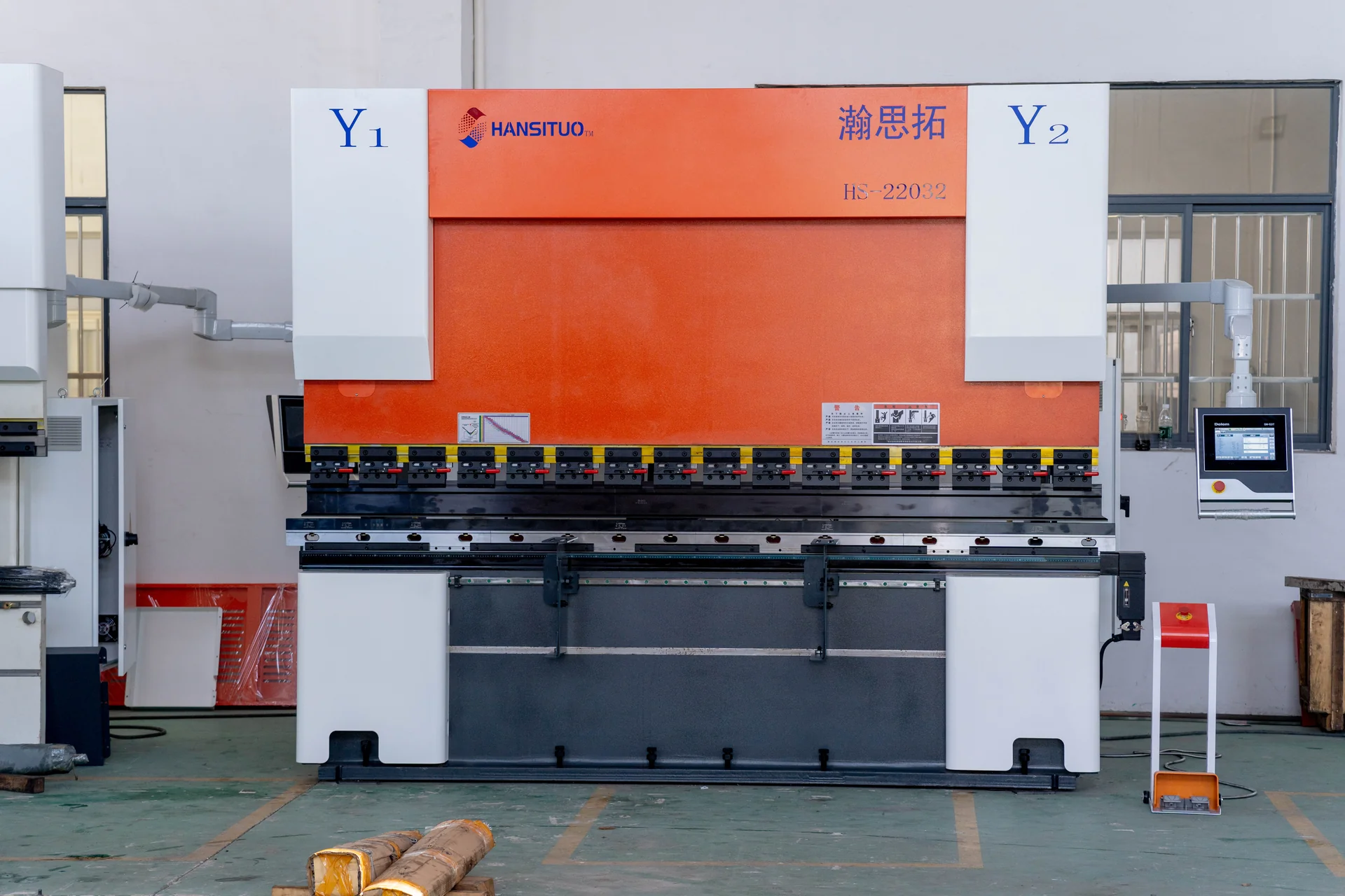
Torsion-Bar Press Brakes for Routine Sheet Metal Forming
Torsion-bar machine · equipment reference
Product Overview
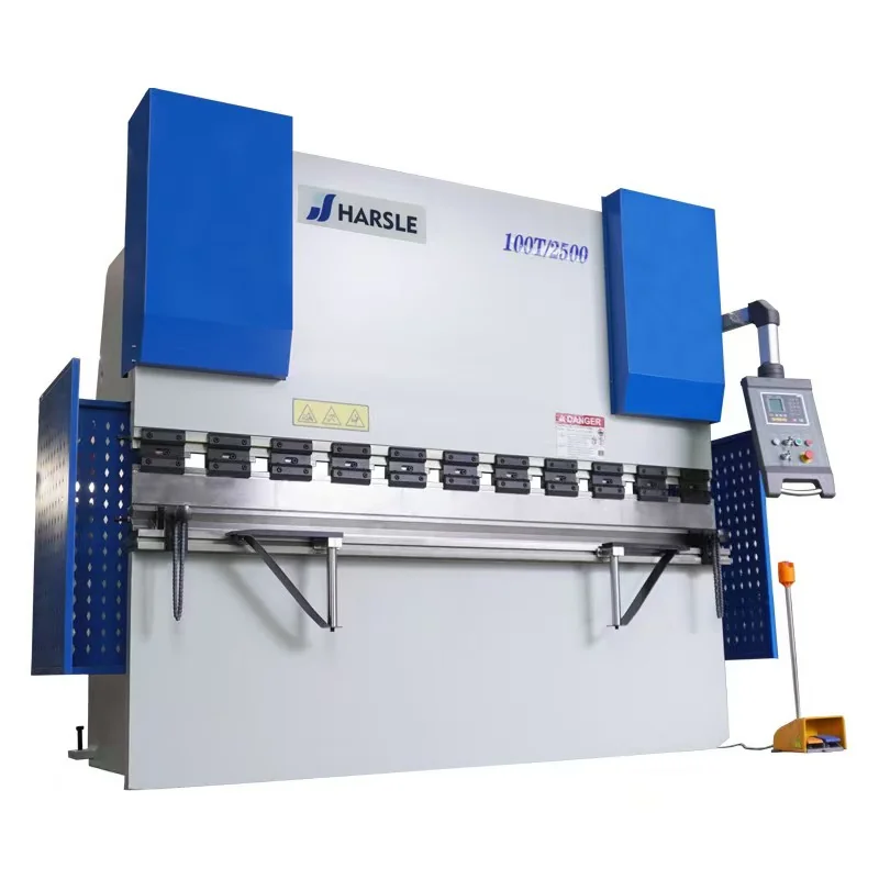
A torsion-bar press brake offers a practical route for bending straightforward brackets, channels, trays and flanged panels. Hydraulic cylinders provide the forming force, while a mechanical linkage coordinates the two sides of the ram. The selected control package sets bend depth and positions the backgauge for the work.
This equipment direction suits workshops whose parts can be produced with accessible tooling, a clear bend sequence and a manageable number of gauge adjustments. CHENDA can help match the machine, control and tool set to those recurring jobs.
Typical applications involve carbon steel brackets, galvanized sheet profiles, stainless steel covers and aluminum components within the selected machine and tool capacity. The material’s grade and condition matter as much as its name: different aluminum tempers tolerate different bend radii, while higher-strength steels increase forming load and springback.
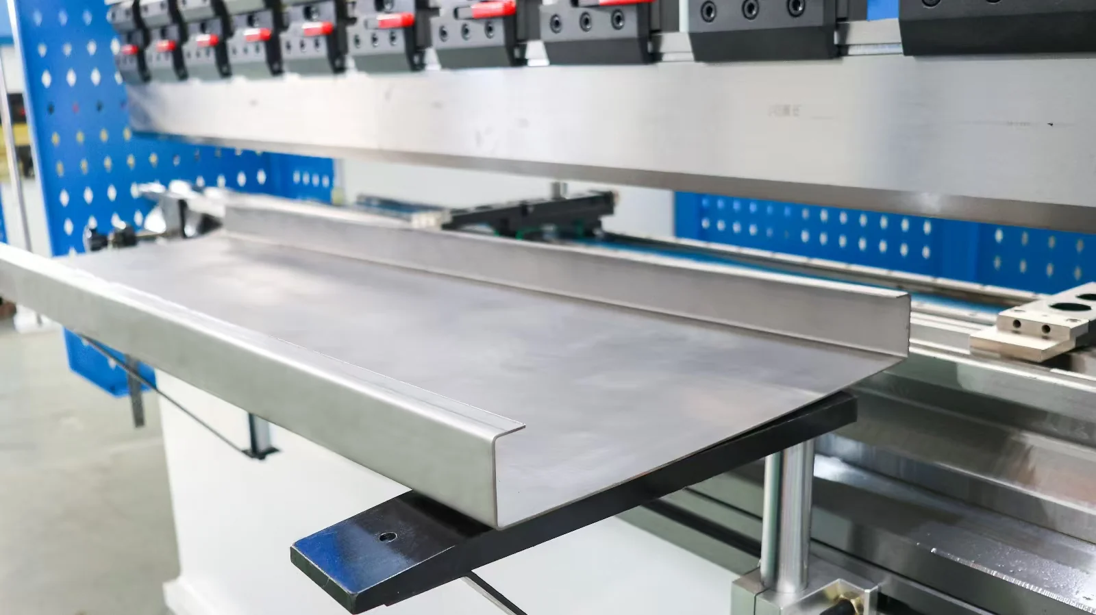
Straight flanges and open channels offer relatively direct tooling access. A closed box, a deep return or a bend near an existing flange may require a different punch profile, segmented tools or another forming sequence. Send the finished drawing to assess those clearances before choosing the machine length.
For a repeated mounting angle, the important dimensions may be the flange height and the distance from a punched hole to the formed face. A flange can have the correct nominal angle while the hole ends up in the wrong assembly position if the blank, bend allowance or locating edge is inconsistent. Stable blank preparation and a repeatable gauge contact let the machine repeat a useful datum rather than repeat an error.
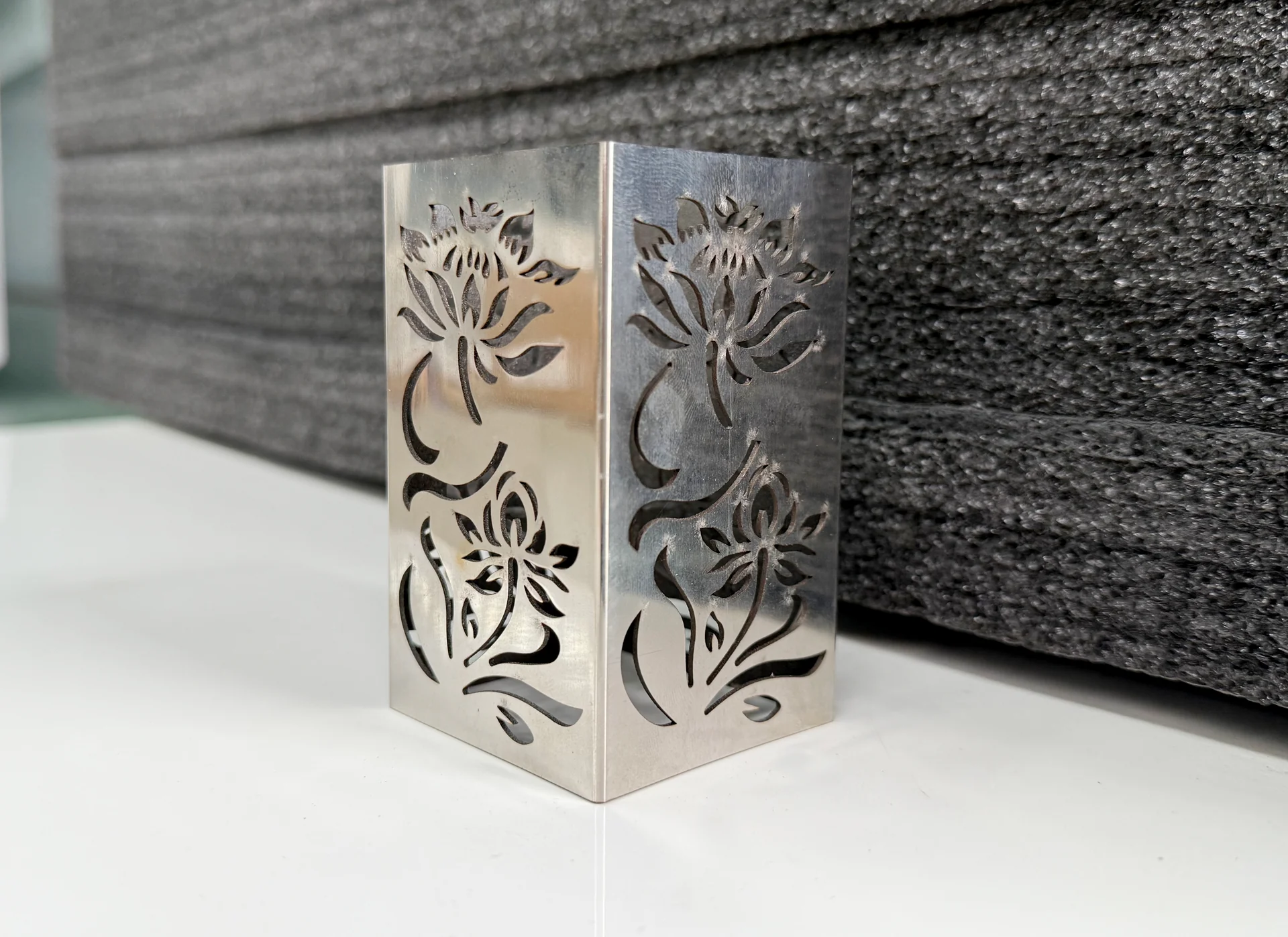
Visible galvanized or stainless faces add another consideration. Material moves across the die shoulders during forming, so debris, surface pickup or an unsuitable contact condition can leave a line even when the dimensions are acceptable. Clean, appropriate tooling and a suitable surface-protection approach address the cause; a different ram-depth setting alone will not remove that marking.
Open channel geometryFormed sheet and visible surfaces
Features & Engineering
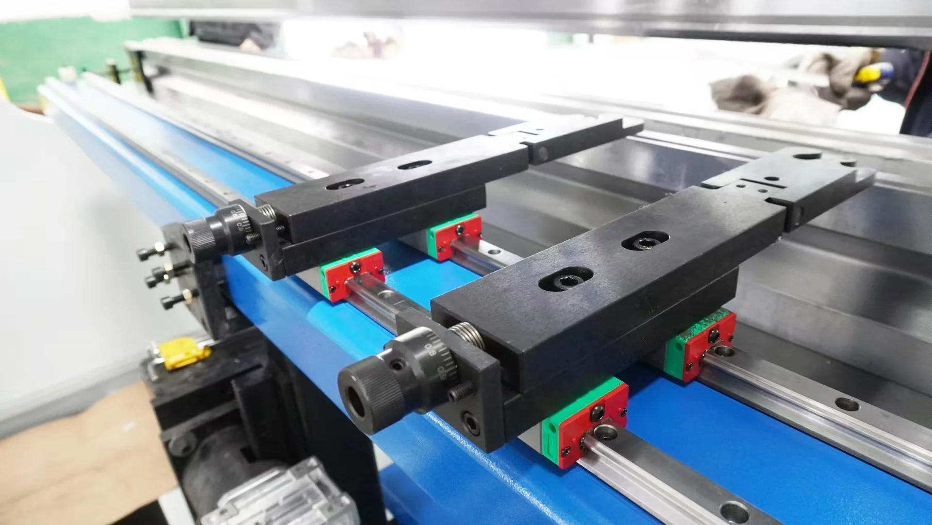
Gauge contact adjustment
Mechanical synchronization
Mechanical-synchronization equipment reference
The torsion-bar arrangement links the ram sides mechanically. Its operating principle differs from independent Y1/Y2 electro-hydraulic control. Alignment, linkage condition and the machine’s permitted loading pattern remain important to consistent forming; avoid treating the machine’s total force as permission to place any load anywhere on the bed.
This architecture gives a clear division of work: the linkage coordinates motion, the depth setting establishes penetration, and the tooling and material determine the bend response. It does not independently measure and correct the angle at every point on the component. That makes a sound initial setup especially valuable for a repeat run. Once the material, tool arrangement and corrections are stable, the operator can reproduce the sequence without rebuilding the process for every piece.
Control matched to recurring work
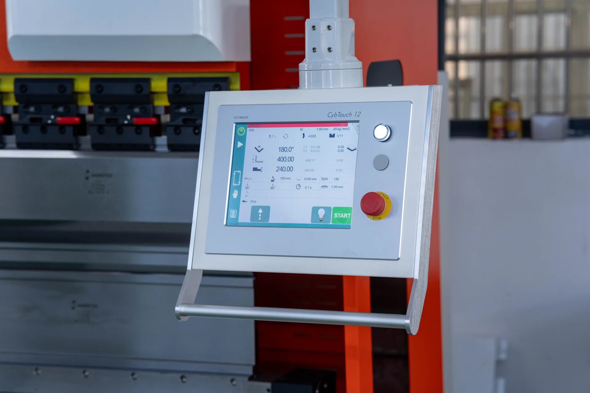
Programmed depth and backgauge positions can make repeated jobs easier to recall. Depending on the selected package, the controller may support a sequence of bends rather than requiring a new setting for every stroke. A touchscreen or CNC-style interface does not, by itself, change the mechanical synchronization system.
Take an open channel with unequal flanges. The depth can remain similar for equal target angles, while the gauge position changes for each flange. A stored sequence removes repeated entry of those positions. If the formed first flange prevents the second edge from touching the same gauge face, however, the job also needs a suitable finger height or another accessible datum. More program memory cannot resolve a physical locating obstruction.
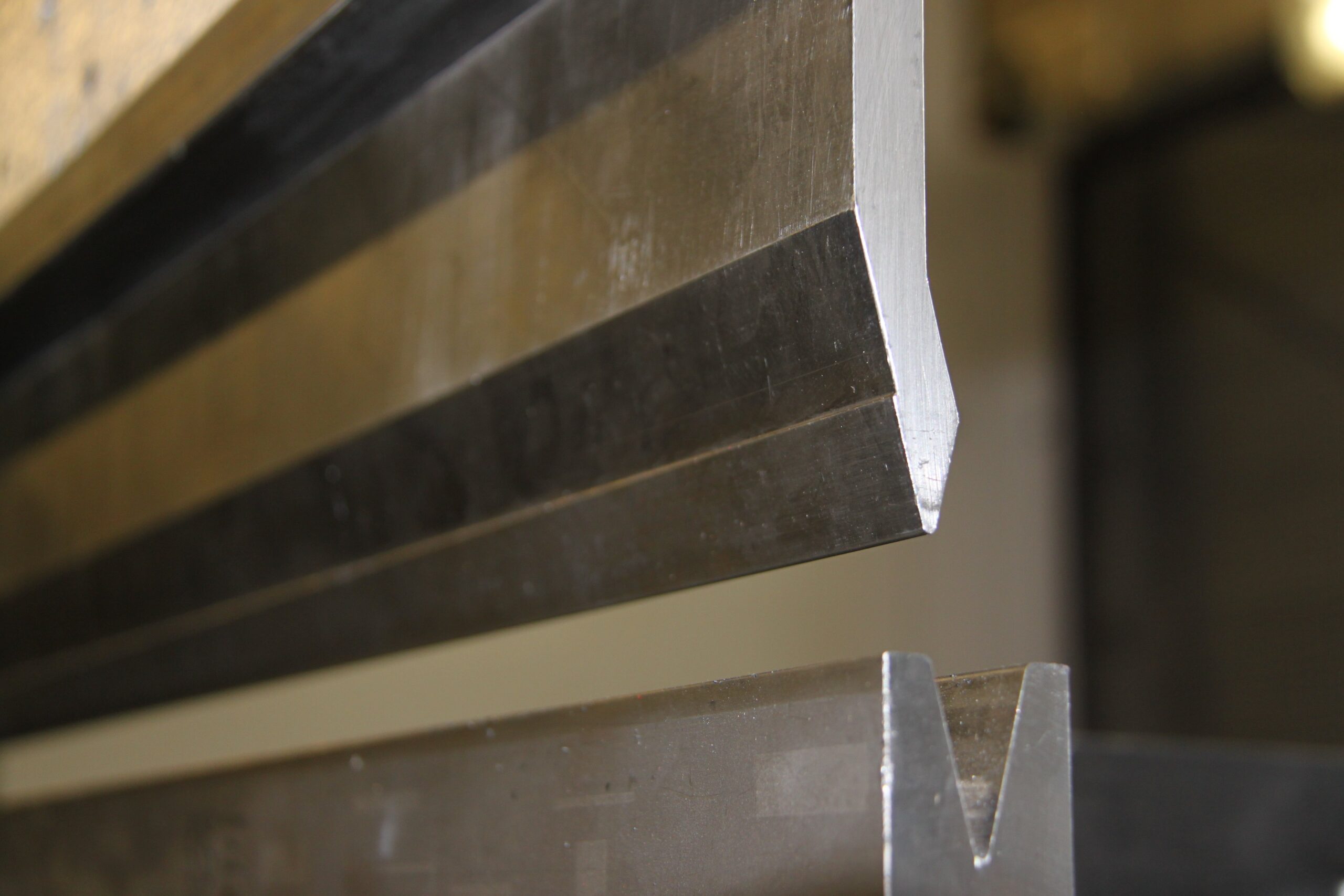
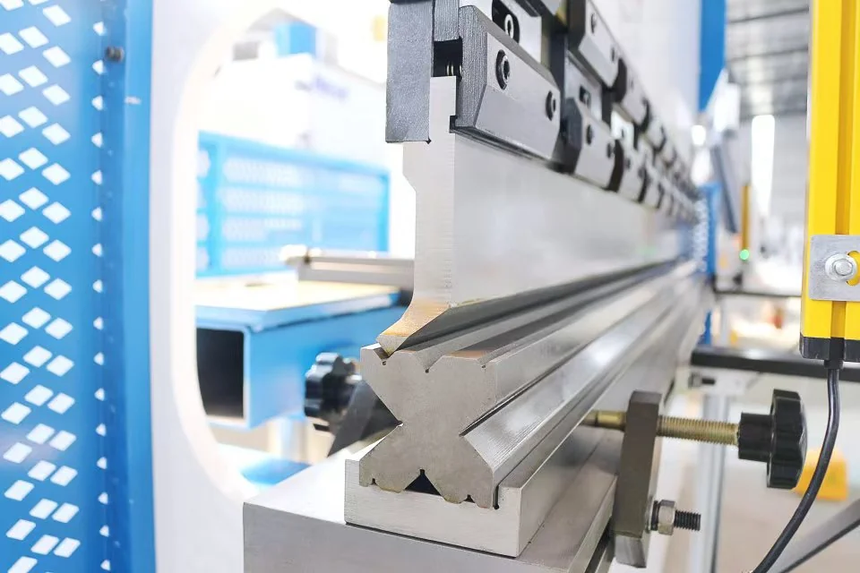
A multi-V die offers different openings for a defined range of work. Smaller openings can help support shorter flanges but increase the required load. Segmented punches help release parts with return flanges. Where long bends require deflection correction, discuss a compatible crowning arrangement and how it is adjusted between jobs.
Changing to another opening on a multi-V die is a process change, not simply a capacity adjustment. Re-establish punch-to-die alignment as required by the machine procedure, update the tool information and check the first part’s radius, angle and flange. For a long batch, this setup work can be spread over many pieces. For a sequence needing several different openings on each component, separate tool stations or a different tooling strategy may be more practical, subject to machine loading limits.
Technical Specifications
The torsion-bar machine is configured from the required force, working length and control package. Request a model-specific data sheet using these fields; thickness capability is assessed against your material and die opening.
Visual reference · to be replaced
Parameter
Unit or format
Selection meaning
Nominal force
kN
Must cover the calculated forming load within allowed load distribution
Bending length
mm
Tool working length required by the longest bend
Distance between uprights
mm
Clearance for wide work inserted between the frames
Throat depth
mm
Space available when a flange passes around the upright
Stroke / daylight
mm / mm
Ram movement / open clearance for tools and the part
Depth control
Axis function and adjustment method
How bend penetration is set and repeated
Backgauge
Axis list; travel in mm
Which positions are automatic and which need manual adjustment
Crowning
Manual, controlled or other quoted arrangement
Method for correcting load-related angle variation
Tooling
Profile, opening in mm and load rating
Form geometry, flange support and allowable force
Confirm the meaning of each axis designation on the quotation. On conventional machines, a Y/X package commonly describes depth and gauge positioning; it must not be confused with independently controlled Y1 and Y2 hydraulic axes.
Working tool length and clamping
Tool length changes the load concentration
A tool’s permitted load is often stated per unit of working length. As a purely arithmetic example, a tool rated at 1,000 kN/m corresponds to 100 kN over 100 mm of fully engaged length, provided its supplier permits that segment and loading arrangement. The press brake, holder or particular tool profile may impose a lower limit. This example is not a CHENDA tool rating.
The distinction matters for short, thick brackets. A machine with ample total force can still overload a small punch segment or holder. Select the machine force and the local tooling capacity together, with the approved loading position and actual engaged length.
Samples & Demonstration
Inspect both flanges from the same datum
Choose a representative channel or bracket with the shortest flange used in normal production. A useful demonstration shows how the operator locates the blank, changes its orientation and clears the tool after each bend. For long parts, measure the angle at several positions along the bend.
Include the expected tool change when setup time matters. Repeat the part after recalling the settings, and check flange size, unloaded angle and any surface marking. This shows whether the proposed control and manual adjustments fit the actual production routine.
For a channel, inspect both flanges from the same defined datum and measure the web width as well as the angles. If the web is wrong but the angles match, changing both bend-depth values risks damaging an otherwise stable angle setup. Trace the blank and locating positions first. A trial record that separates these measurements makes later production corrections faster and more consistent.
Discuss the package in terms of the work it removes from the operator:
Depth and gauge control: select the program functions needed for recurring parts and multi-step jobs.
Gauge fingers: choose usable contact faces and height adjustment for the flange sequence.
Punch and die set: specify working lengths, segmented sections, V openings and special profiles.
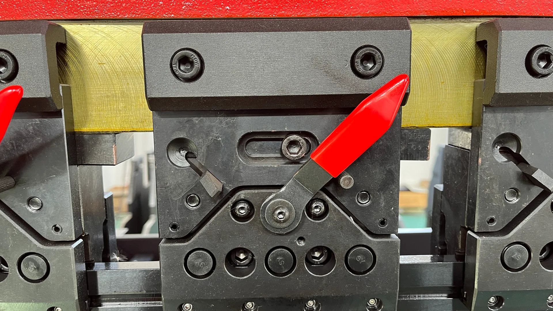
Tool clamping: compare the available manual and quick-change arrangements with tool-change frequency.
Front supports and crowning: match support positions and compensation method to panel size and bend length.
Manual finger positioning, tool clamping or compensation may be appropriate for simple batches. Where these adjustments consume substantial time across mixed work, compare an electro-hydraulic CNC configuration. Included equipment and any upgrades are itemized in the proposal.
For recurring long channels, front supports and an accessible gauge can matter more than additional software functions. For batches of short brackets with several profiles, segmented tooling and quick clamping may remove more non-production time. Build the package around the action that repeats most often: lifting, locating, changing tools or changing settings.
The channel is the inspection reference
Applications & Workflow
For channel production, cut the blank to a controlled width, remove burr that interferes with the gauge contact, form the first flange, then reposition for the second. Check channel width and angle together: correcting the angle alone can still leave an assembly that does not fit.
For brackets, organize tools and blanks by material and thickness so that the setup remains consistent. Recheck the first piece after changing a material batch or die opening. Grouping compatible parts can reduce repeated setup without mixing drawing revisions.
Allow space behind the machine for gauge access and maintenance, and in front for the blank to swing upward during forming. Plan tool lifting and storage as well as machine unloading. A long panel may require more operating space than the machine footprint suggests.
Commissioning should establish the machine’s level, reference settings, hydraulic condition, gauge alignment and operation of the supplied protective functions. Training should include safe tool changes, acceptable loading, bend correction and the scheduled inspection of the synchronization mechanism.
Retain the accepted setup with tool identification, material and the measured result. If a later batch behaves differently, those records distinguish a changed material response from altered tooling or gauge settings. Agree the supplied tools, loose support components and documentation through the production and delivery handover, so that the tested arrangement can be identified after receipt.
Ask for the proposed machine sheet, control function list, tooling drawing and installation layout. If existing punches or dies will be reused, provide their interface dimensions and load ratings; similar appearance is not proof of compatibility.
Yes. Conventional press-brake controllers can provide programmed depth, gauge movements and other functions. The controller label does not mean the ram sides use independent electro-hydraulic synchronization.
Visual reference · to be replaced
Is it suitable for many different small batches?
It can be when tooling access is straightforward and manual adjustments are limited. If every part requires frequent finger-height changes, complex re-gauging or graphical sequence checks, compare the time required with a more fully controlled machine.
Visual reference · to be replaced
Why does the middle of a long bend differ from its ends?
Possible causes include deflection under load, tooling condition, setup and material variation. Crowning addresses a particular deflection pattern; first confirm the source of the variation rather than applying an arbitrary correction.
Visual reference · to be replaced
Can we bend a short thick part at full machine force?
Only within the machine and tool loading limits. A concentrated load can exceed the permitted force per unit length even when it is below the press brake’s total rated force. Have the proposed setup checked.
Visual reference · to be replaced
Does a torsion bar rule out all off-center bending?
No blanket rule should replace the machine’s loading instructions. Permitted position and load depend on its design and rated conditions. Electronic synchronization is not permission for unrestricted off-center loading either; the frame, ram, cylinders and tools still have limits.
Send the material, thickness, bend length, finished profile and normal batch size. Tell CHENDA how often you change tooling and which adjustments currently take the most time. Include photographs and dimensions of any tools you want to retain.