Sheet metal / Edge & surface finishing

Deburring and Finishing Machines for Sheet Metal Parts

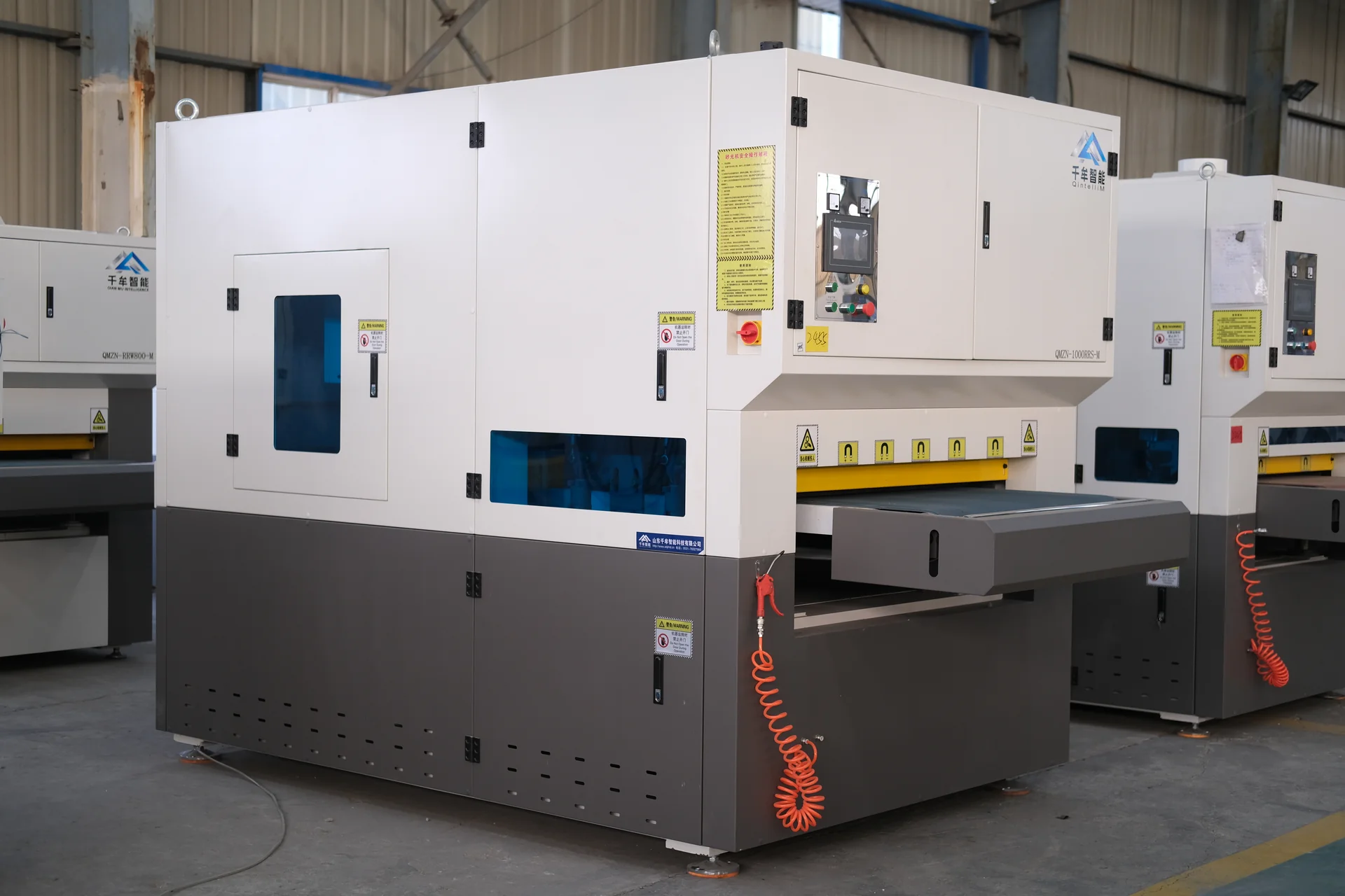
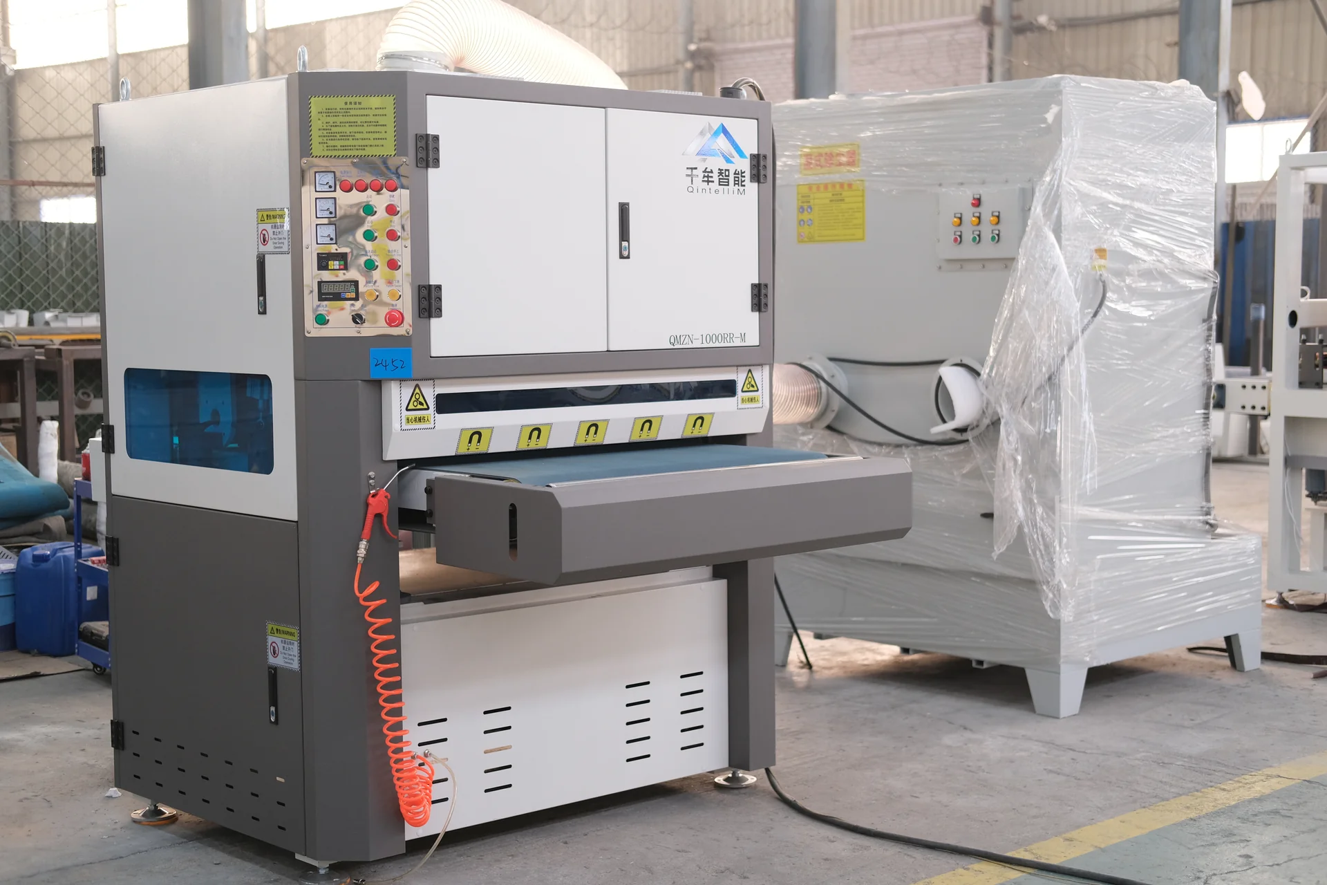
Front-left view of an enclosed deburring machine with an infeed conveyor and blue side windows.
Wide-belt finishing architecture · equipment reference

Product Overview

Turn a cut blank into a part that is easier to handle, assemble, coat or present. CHENDA deburring and finishing equipment is selected around three distinct requirements: removing raised burr, conditioning sharp edges and creating a controlled surface finish. Bringing the correct abrasive operations into a repeatable route can reduce repeated hand grinding and make the outgoing condition easier to control across a batch.

A laser-cut cabinet panel may need light edge rounding without damage to its visible face. A thick plasma-cut bracket may need substantial slag removal first. A stainless cover may need a consistent grain. Treating these as the same task can create unnecessary stock removal, poor finish or excessive consumable use.

The most useful configuration is the one that produces the required edge and face together, with practical loading and consumable changes. A machine that removes a burr quickly but leaves a second manual finishing operation may not resolve the production bottleneck.

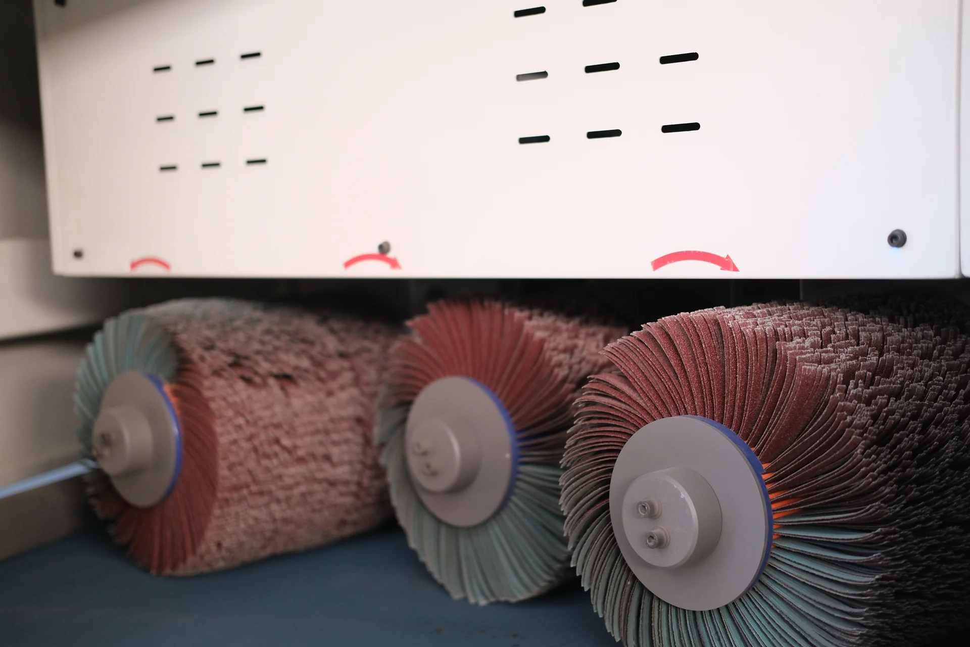
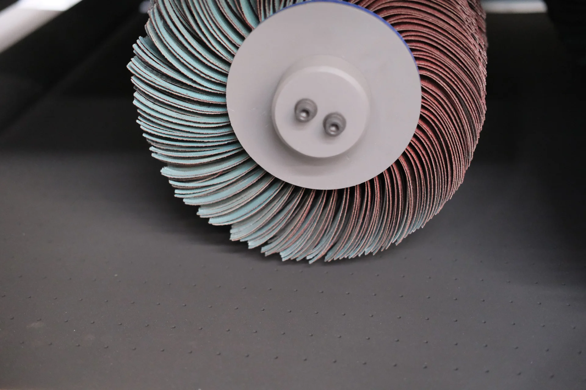
Three cylindrical abrasive flap brushes beneath a guard with red direction arrows.
Abrasive contact determines the edge and face result

Materials & Capabilities

Common workpieces include flat steel brackets, stainless panels, aluminum covers, punched blanks and laser- or plasma-cut components. Suitability depends on the incoming burr, flatness, geometry, material and ability to retain the part securely during processing.

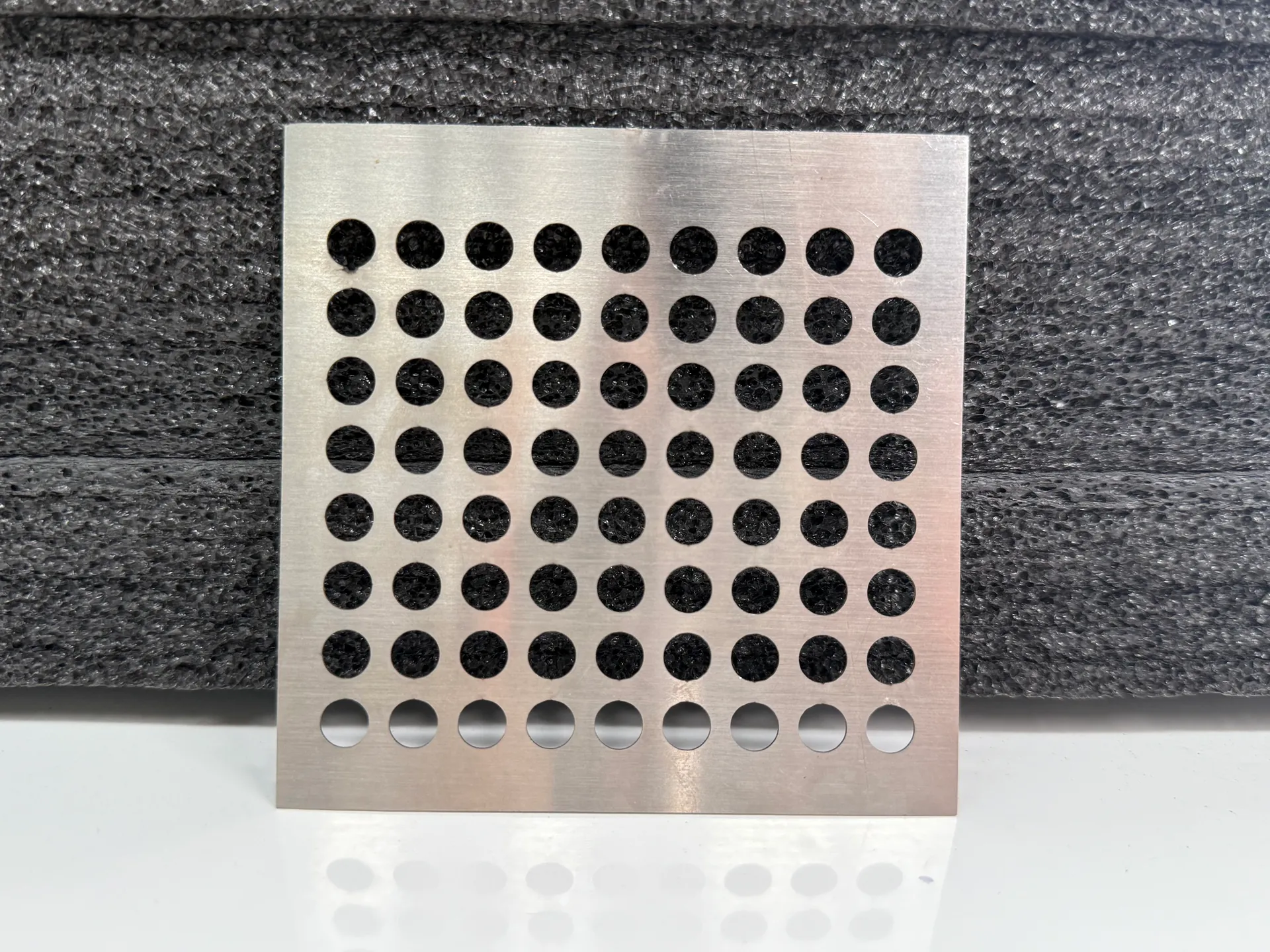
Metal sheet sample with a regular array of circular holes
Openings and flatness are part of the incoming-part assessment
Incoming condition Required operation Result to define
Raised burr above the sheet face Deburring Remaining burr height and acceptable face removal
Sharp perimeter and hole edges Edge breaking or rounding Edge condition or radius, including internal contours
Heavy adherent dross Slag-removal stage Removal without overloading finer finishing units
Oxide on cut edges Suitable edge-cleaning process Required oxide condition for the next operation
Inconsistent visible face Surface finishing Grain direction, scratch pattern and approved appearance

Coated, galvanized or film-protected sheets need their own assessment. A machine that can process bare metal may remove a coating or mark protective film. Formed parts, protruding features and deep recesses also require an access and hold-down review rather than an assumption that every surface will be reached.

Features & Engineering

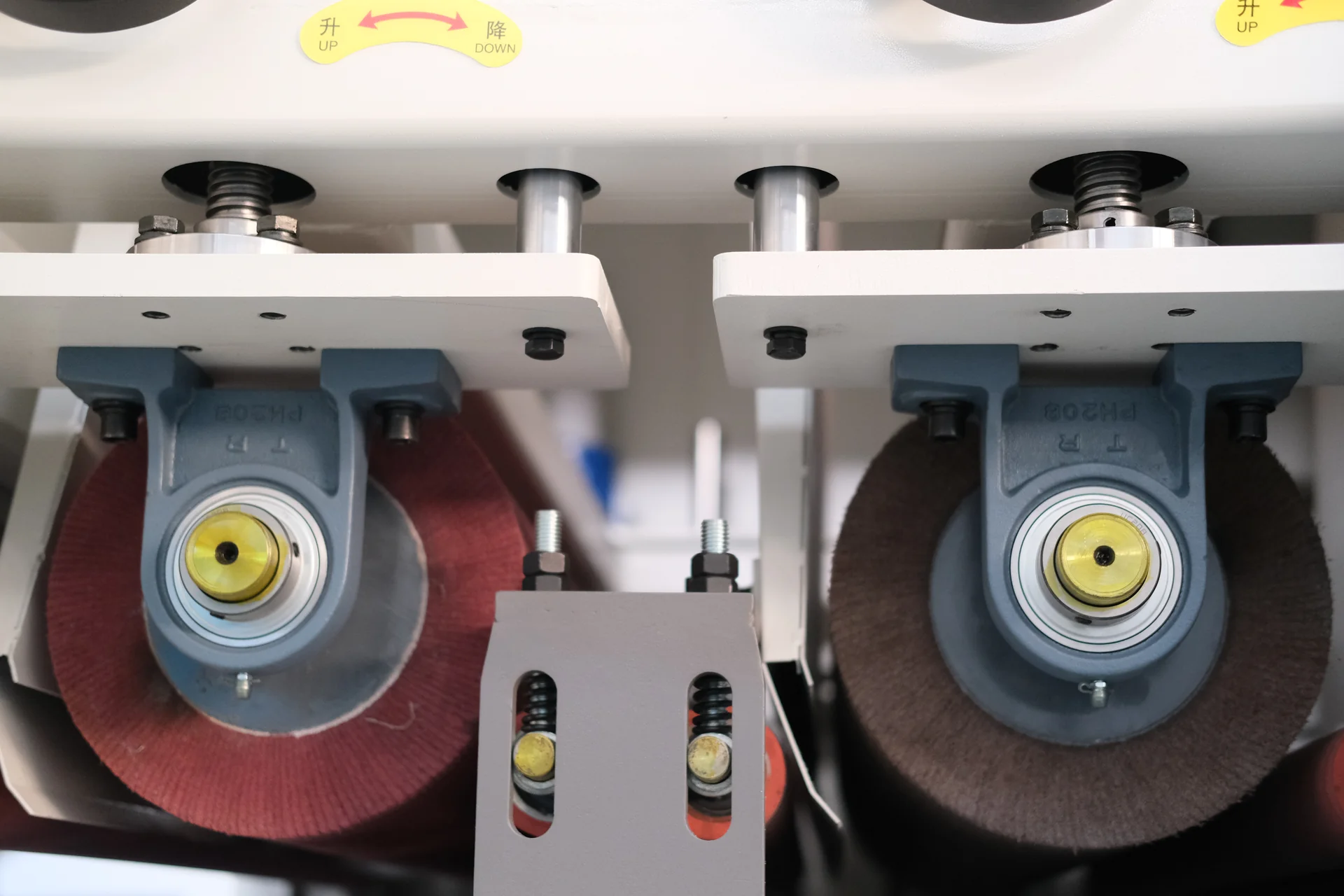
Paired abrasive wheels with bearing housings, adjustment screws and spring-loaded supports.
Abrasive unit and height adjustment · reference
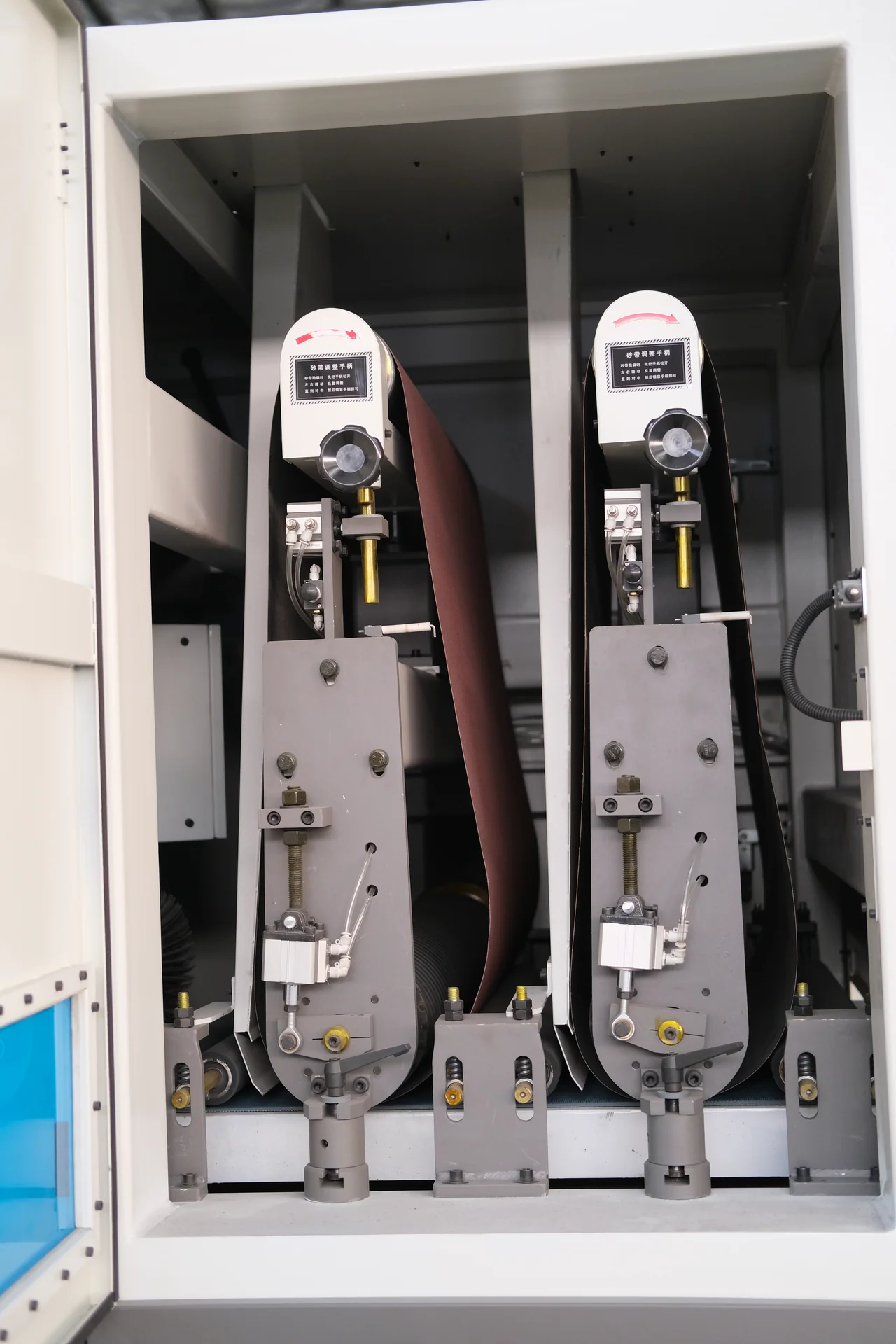
Two wide abrasive belt assemblies inside an open side compartment.
Belt assemblies · removal-contact reference

Use the right contact for the defect

An abrasive belt can remove material from a raised burr and work the sheet face. A compliant brush or suitable edge-rounding unit reaches edges differently and can reduce sharpness around contours. A dedicated heavy-slag stage may be needed before either. Combining units can reduce handling, but the station order must match the required edge and surface result.

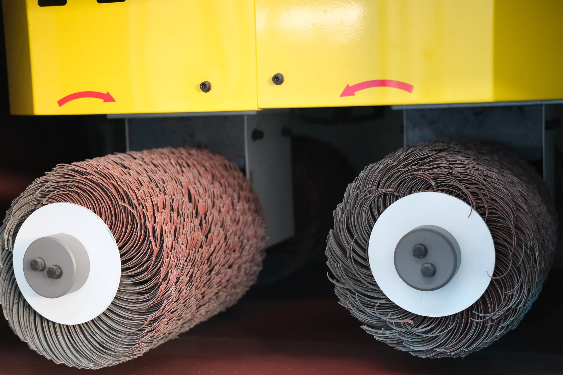
Two abrasive brush rollers beneath a yellow guard with rotation-direction arrows.
Brush rollers · edge-contact reference

Why station order changes the finished part

Three cylindrical abrasive flap brushes beneath a guard with red direction arrows.
Unit arrangement must follow the required finish
Process priority Station logic to evaluate Consequence for the part
Burr removal followed by touch-safe edges Removal belt followed by a suitable rounding unit The first stage reduces the projection; the second works the exposed edges
Consistent grain after rounding Edge treatment followed by a suitable finishing belt The final station establishes the visible face pattern
Heavy cut dross followed by finer finishing Dedicated initial removal before finer abrasives Avoids using a finish-oriented station for the entire removal load
Coated face with exposed sharp edges Edge-focused contact validated with the coating Preserves the face only within the tested process window

These are process architectures, not interchangeable head labels. Brush arrangement, contact direction and part geometry determine access to internal holes and contours. A finished outside edge does not prove that a narrow slot received the same treatment.

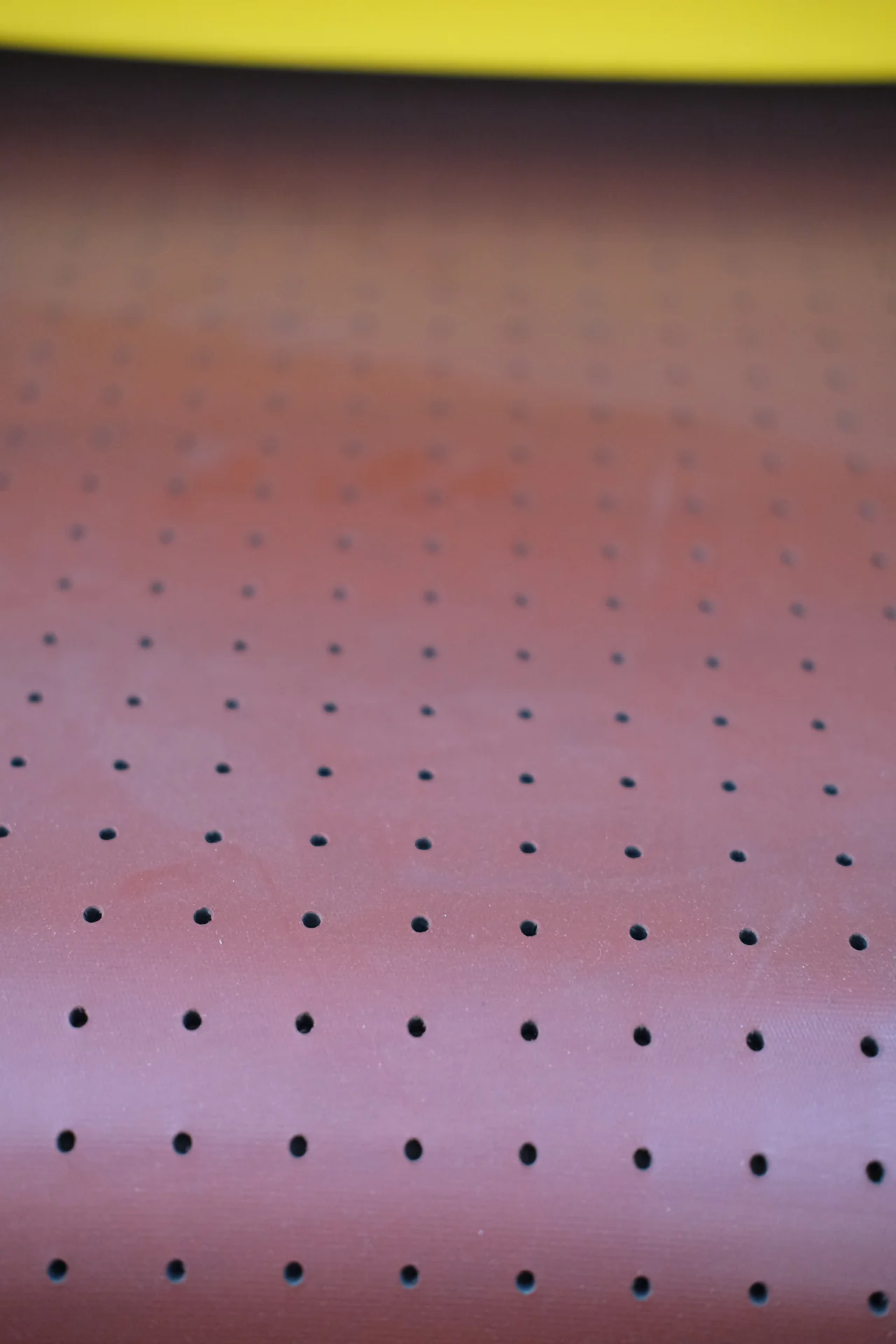
Close-up of a red perforated conveyor belt surface.
Perforated conveyor surface · retention arrangement requires confirmation

Keep small parts stable

Part retention limits useful capacity just as much as working width. Contact area, openings, thickness and shape affect how securely a part travels through the machine. Vacuum retention may help suitable nonferrous parts; magnetic retention applies only to suitable ferromagnetic material and configurations. Neither approach makes every small part acceptable. Test the smallest, most perforated and least stable production shapes.

A broad perforated grille can be harder to retain than a smaller solid plate because there is less effective area for hold-down. Narrow strips also give contact forces more opportunity to turn or lift the part. This is why a minimum-part-size statement needs a shape and retention condition. A carrier or special fixture, where supported, changes the feeding arrangement and should be included in the trial rather than improvised after installation.

Separate finish control from stock removal

Feed rate, contact pressure, abrasive type and abrasive condition influence the result. A coarse removal stage can leave scratches that require later refinement. A finishing pass can change visible grain without delivering the edge radius required for coating. Define both outcomes where both matter.

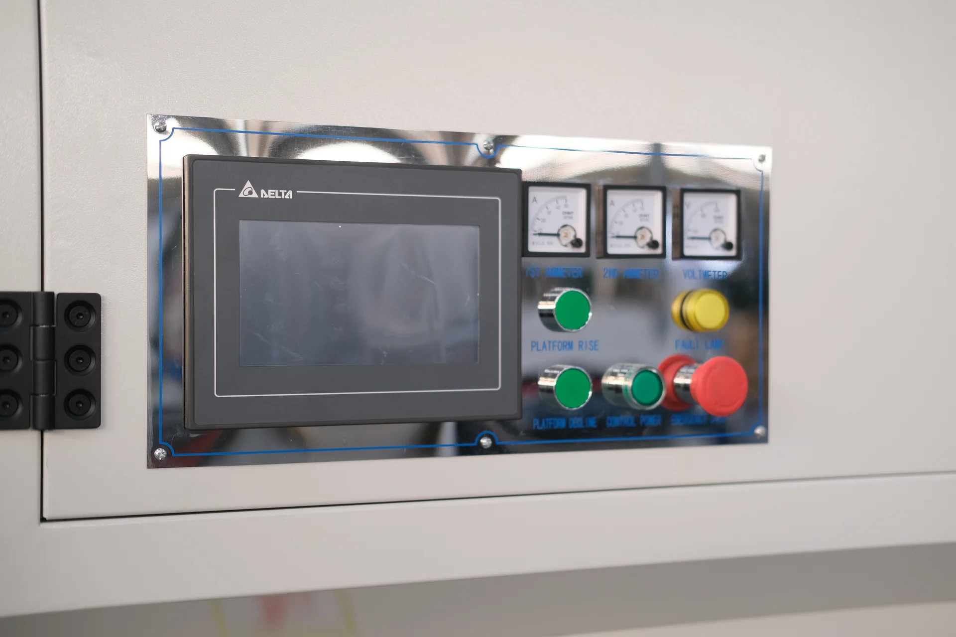
Deburring-machine operator panel with a Delta HMI, analog meters, pushbuttons and an emergency stop.
Adjust the process with a defined outgoing reference

Maintain a finish as abrasives wear

Fresh and worn abrasives do not cut identically. The working contact changes as brushes wear, while a belt can become loaded with removed material or lose cutting effectiveness. Increasing contact pressure to compensate can change the face finish or heat the part. A useful operating routine therefore tracks the reference sample, abrasive identity and adjustment, then replaces the consumable when the process can no longer hold the required result.

Use of the conveyor width also matters. Feeding every part through the same narrow lane can concentrate wear. The permitted loading pattern should distribute work while retaining stable feed and the required spacing. This is a production practice to establish with the selected machine, not a universal instruction to place mixed parts anywhere on its belt.

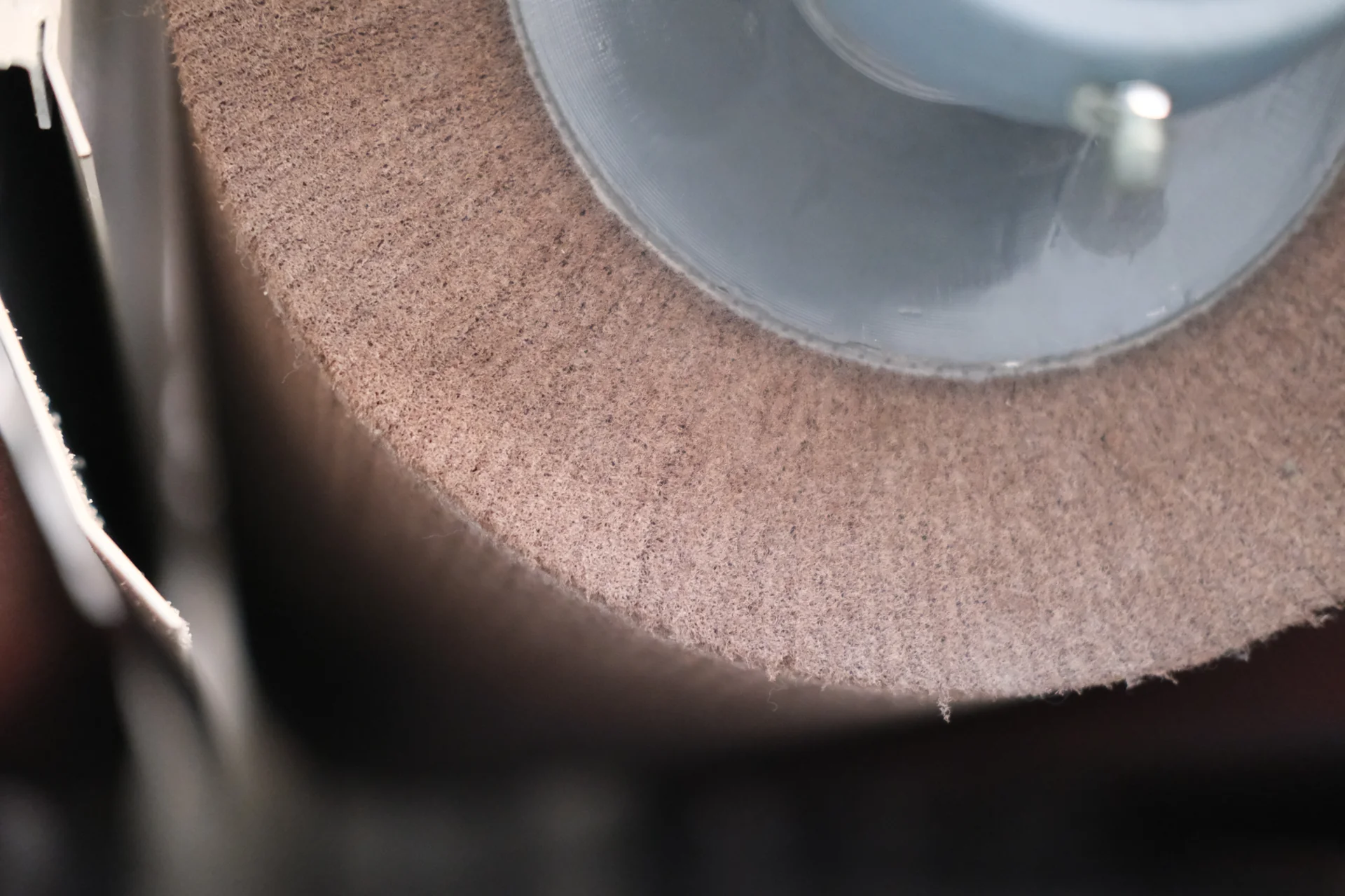
Close-up of a brown fibrous abrasive wheel and part of its metal hub.
Abrasive texture
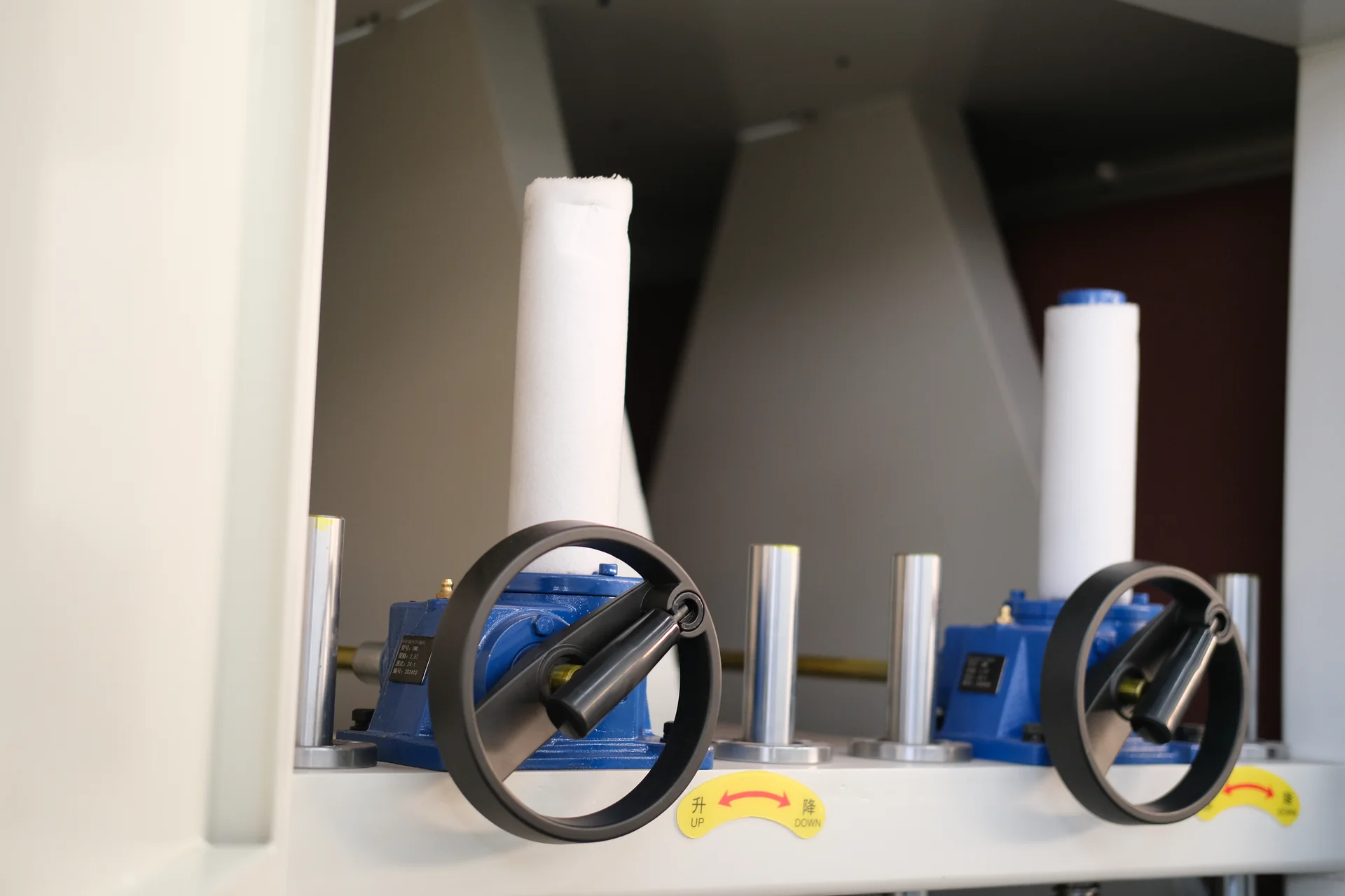
Two manual adjustment handwheels with blue gearboxes and vertical screw assemblies.
Mechanical adjustment reference

Technical Specifications

Select a machine around the part envelope and process units below. Width, thickness and feed-speed limits are supplied for the proposed model; a family name alone does not define those capacities.

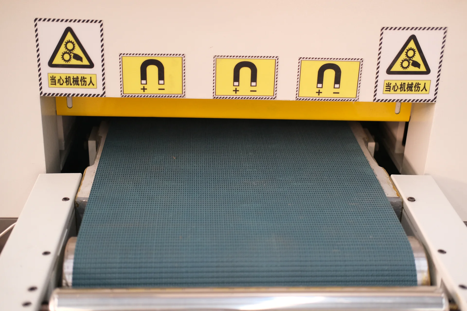
Green infeed conveyor below a yellow guard and mechanical-hazard warning labels.
Usable feed opening and part support · reference
Specification Unit Selection condition
Usable processing width mm Include part orientation and the largest production blank
Part thickness / opening mm State minimum and maximum usable thickness, including retention limits
Minimum processable part L × W, mm Confirm shape, material, perforations and hold-down method
Incoming burr or slag mm; description Identify height, attachment and whether a removal stage is needed
Edge radius or edge condition mm; agreed reference Define outer edges, holes and both faces where required
Conveyor speed m/min Evaluate with the required finish and number of passes
Processing units Type and sequence Distinguish belts, brushes, rounding and slag-removal functions
Abrasives Dimensions, grit and type Specify consumable identification and replacement method
Surface requirement Ra in µm where relevant; visual reference Roughness and appearance may require separate acceptance criteria
Utilities and extraction kW; air and extraction requirements State the selected machine and collection system together

Model comparison should use the same incoming sample and outgoing requirement. A wide machine with a fast conveyor may still need multiple passes or manual reversal to finish both sides.

Samples & Demonstration

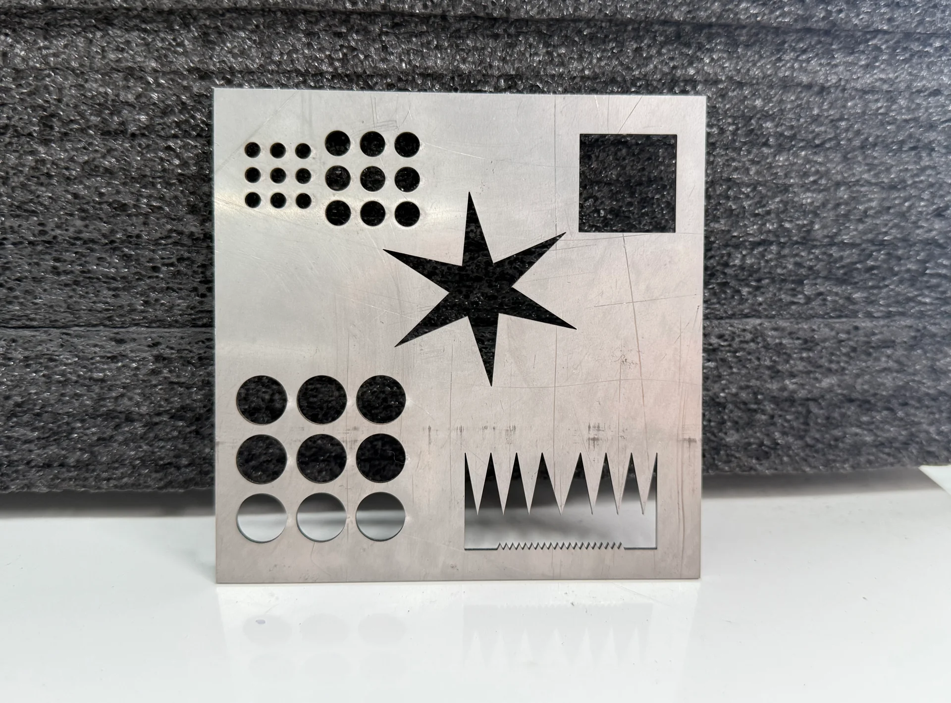
Metal cutting sample with round holes, a square opening, a star and narrow triangular cutouts
Cut-blank geometry · incoming-sample reference
Metal sheet sample with a regular array of circular holes
Include internal openings in the trial

Send representative parts directly from the cutting or punching process, including difficult internal openings and the smallest part. Add a sample of the visible finish or protective film that must remain acceptable.

The trial should compare the incoming edge with the finished perimeter and holes. Check both faces, corners, thickness change and surface appearance. Where a radius is specified, agree the measuring method and locations. Record abrasive sequence, feed setting, passes and orientation. A favorable result on a large solid coupon does not establish performance on a small perforated part.

For a stainless enclosure panel, inspect the surface under the lighting and viewing direction used for the assembled cabinet. A consistent roughness value does not necessarily make two differently directed scratch patterns look alike. For a precision slot, inspect the opening after edge treatment because local material removal can change its entrance geometry. For a coated part, examine film edges and the underlying finish, not only the burr.

Configuration & Options

Discuss the station combination before treating an accessory list as a standard package. Depending on the task, a proposal may include abrasive belts, edge-rounding brushes, suitable oxide-removal tools, part-retention equipment, infeed and outfeed support or a return-handling arrangement.

Dry processing with dust extraction and wet abrasive processing are different system choices. A wet dust collector connected to a dry machine does not turn the machining process into wet grinding. Specify the material mix, dust characteristics, collection method, cleaning access and maintenance responsibilities together. Mixed-metal operation may require separate abrasives and cleaning procedures to control cross-contamination.

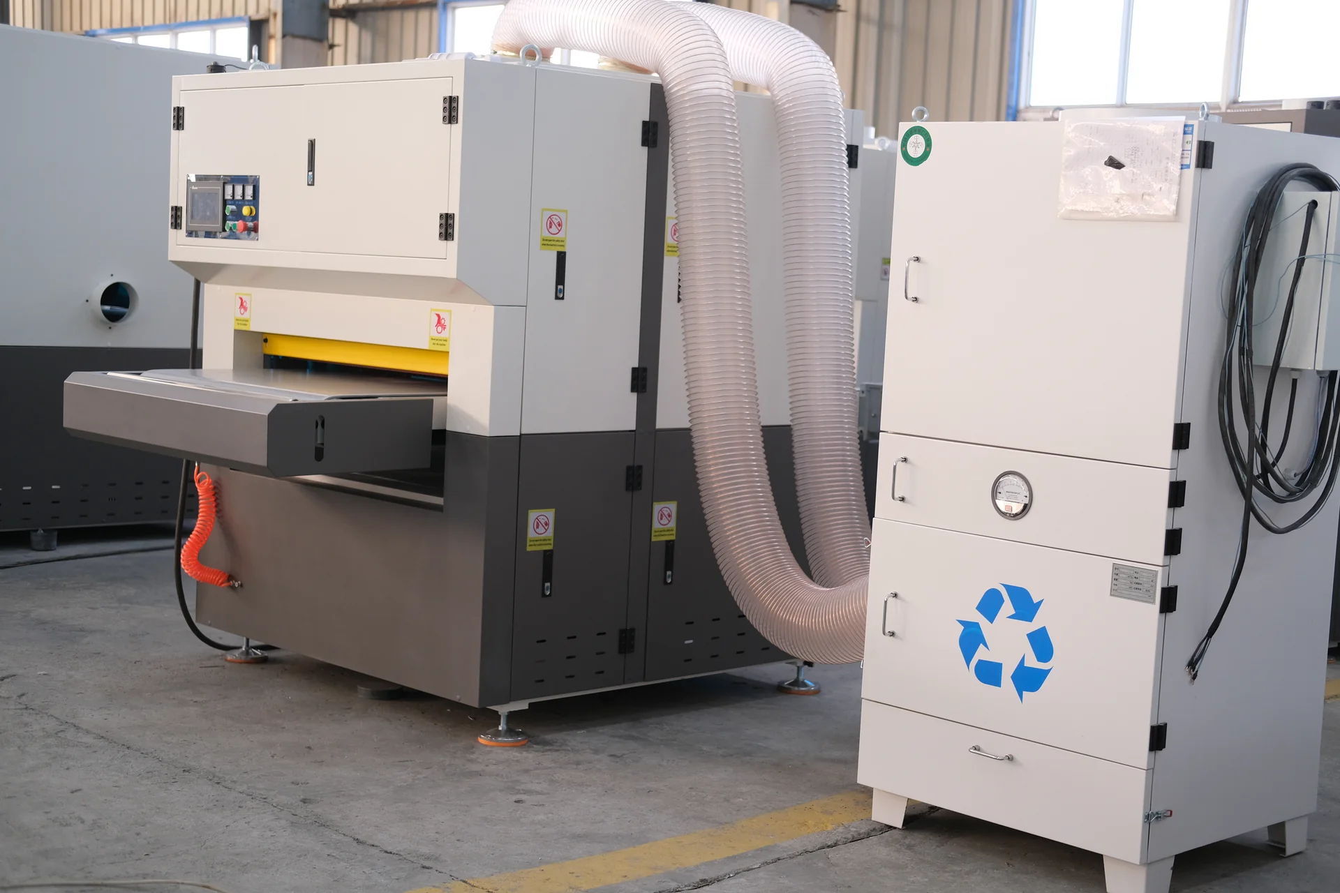
Deburring machine connected to an adjacent extraction cabinet by two flexible hoses.
Machine and extraction arrangement · system reference

Include a starting abrasive set and the information needed to reorder it when these are part of the quotation. Consumable cost depends on the incoming burr and agreed finish, so a service-life promise without the application is not a useful comparison.

The dry-versus-wet decision should also include the work after grinding. Wet processing can create a need for part drying, fluid management and appropriate protection of susceptible metals. Dry processing requires dust capture matched to the material and operating conditions. The equipment layout and housekeeping method must support the chosen route; a dust-system label alone does not establish suitability for every metal mixture.

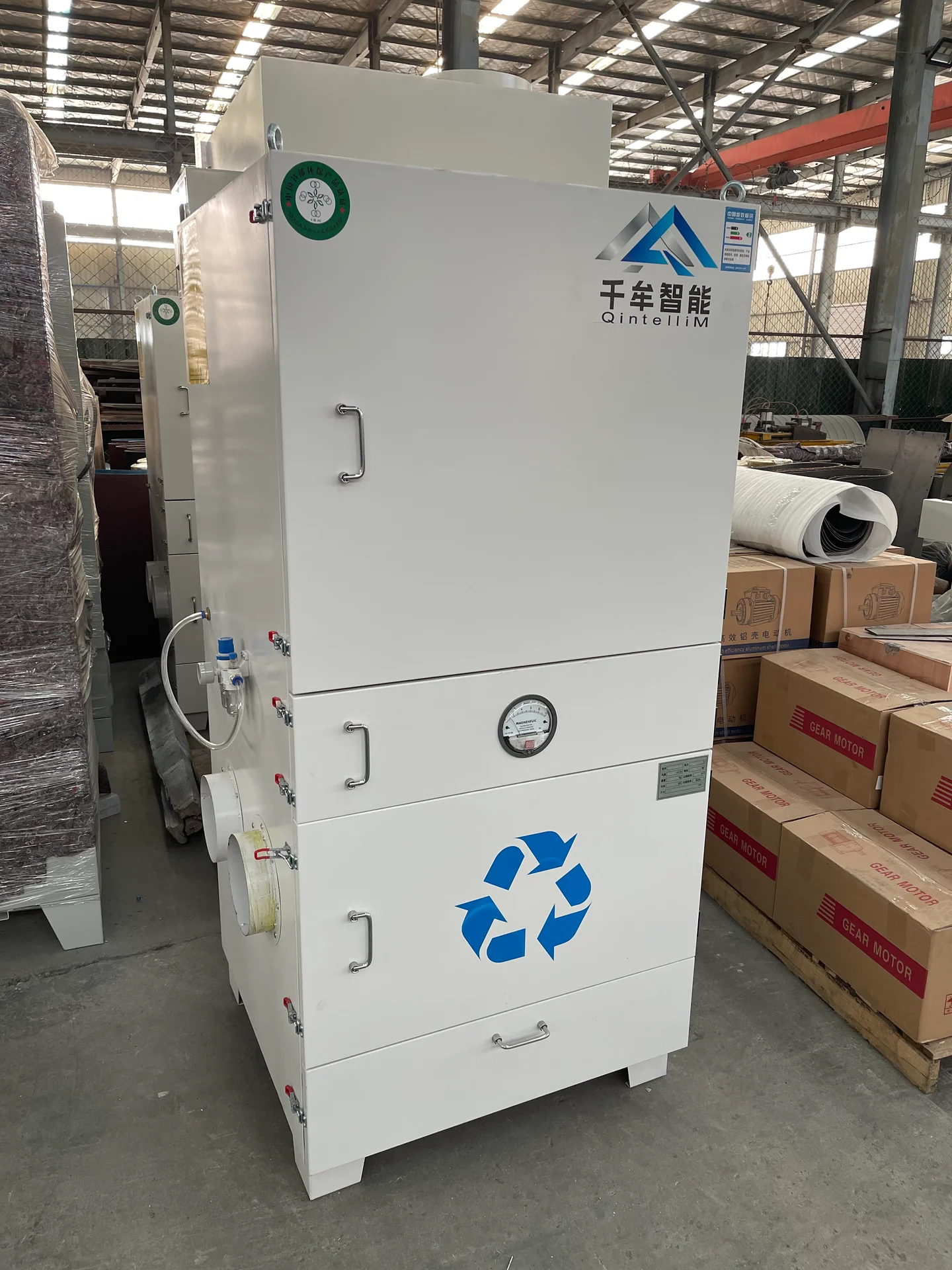
Freestanding dust extraction cabinet with a front pressure gauge, access panel and lower collection drawer.
Dust collection is a separate system choice

Applications & Workflow

Painted metal filing cabinets with open drawers
Sheet-metal cabinet application reference

In sheet-metal fabrication, deburring commonly follows cutting and precedes bending or assembly. This places edge work while the part is still flat and accessible. The route may change when a decorative finish must be applied after another operation.

For powder-coated components, discuss edge preparation with the coating process owner. For stainless cabinets, coordinate grain direction across adjoining faces. For welded assemblies, keep the processed surface free from abrasive residue or incompatible contamination before fit-up.

Sort production by material and thickness where required by the selected machine. Retain an approved finished sample and inspect the result as abrasives wear. Changes upstream in cutting can change the burr load even when the finishing recipe has not changed.

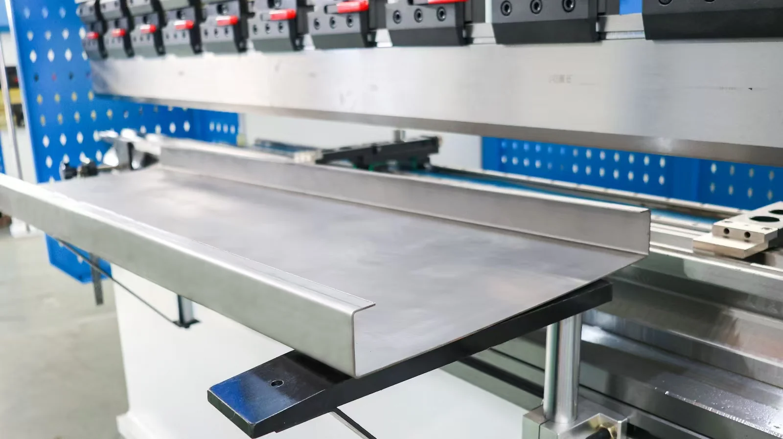
Formed sheet-metal channel resting on the front supports of a press brake.
Formed sheet-metal geometry · downstream-operation reference

For an electrical enclosure, edge work before bending leaves the blank easy to feed and gives access to cutouts that become difficult to reach in the formed box. The operation must preserve useful gauge edges and surfaces used by the press brake. For a visible stainless cover, the sequence must also preserve a common grain direction after forming. Those handoffs connect finishing performance to final assembly quality rather than judging the machine only by a burr-free photograph.

Installation & Support

Allow space for the full length of parts entering and leaving the conveyor, abrasive replacement, dust-collection service and safe part handling. Confirm electrical supply, extraction connections, floor conditions and any compressed-air requirement for the proposed machine.

Training should cover thickness setup, retention, permitted part sizes, abrasive selection, feed adjustment, cleaning and inspection. Maintenance records should identify belt and brush types as well as replacement dates so a finish change can be traced to its cause.

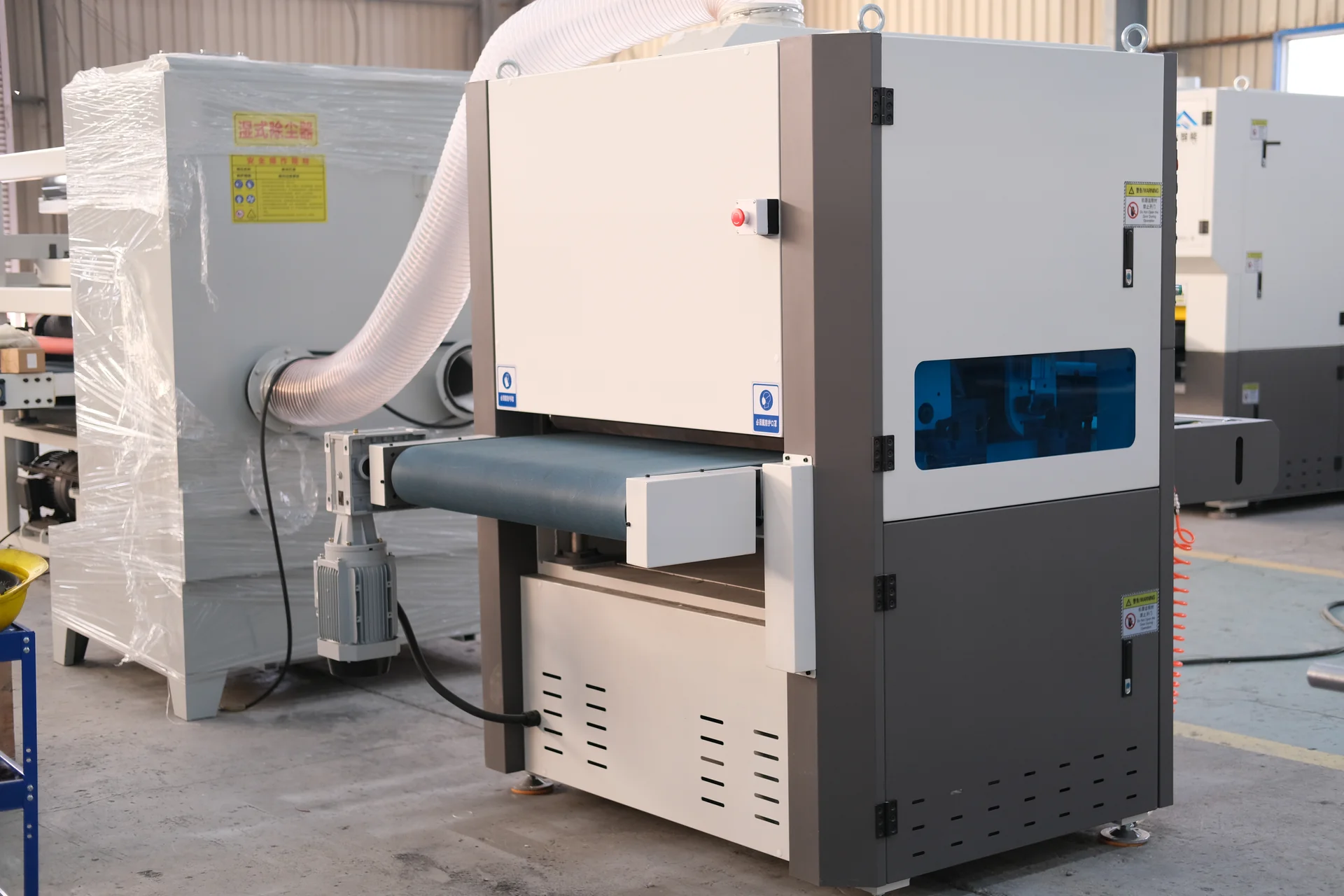
Rear three-quarter view of a deburring machine showing its conveyor drive and extraction connection.
Retain access to the equipment service side
Three cylindrical abrasive flap brushes beneath a guard with red direction arrows.
Identify the abrasive set and replacement requirements

Technical Resources

Request the processing-unit diagram, capacity sheet, minimum-part conditions, abrasive schedule and extraction requirements. For coated or visible parts, ask for a trial record tied to the approved surface sample.

Product FAQs

Close view of alternating red and green abrasive flaps around a brush hub.
Abrasive-contact reference
Two abrasive brush rollers beneath a yellow guard with rotation-direction arrows.
Brush contact reference

Are deburring and edge rounding the same operation?

No. Deburring removes an unwanted projection; rounding changes the edge geometry. A part can be free from visible burr and still have a sharp edge.

Two wide abrasive belt assemblies inside an open side compartment.
Station architecture reference

Can one pass finish both faces?

That depends on the machine architecture and process units. A single-sided system may need the part reversed. State which edges and faces need treatment when defining the cycle.

Close-up of a brown fibrous abrasive wheel and part of its metal hub.
Abrasive identification reference

Can we process stainless steel after carbon steel?

The material route needs a contamination-control plan. Separate abrasives, cleaning and handling may be necessary, especially where the stainless surface has appearance or corrosion-performance requirements.

Deburring machine with a vertical control panel, front conveyor and white access doors.
Confirm the proposed process units

Can the machine remove heavy plasma slag?

Possibly with an appropriate initial removal stage. Submit actual parts; heavy adherent slag can overload a configuration intended for light burr and final finishing.

Close-up of a red perforated conveyor belt surface.
Part retention reference

Does working width determine the minimum part size?

No. Retention, contact forces, thickness and geometry govern the smaller limit. A narrow strip or highly perforated part can be harder to retain than a compact solid part of similar dimensions.

Request a Quote

Send material grades, thickness range, largest and smallest part drawings, the cutting method, close-up edge photographs and the required outgoing condition. Identify protected or visible surfaces, material changes, daily workload and whether both faces must be processed. This provides the basis for a station sequence and sample plan.

Metal cutting sample with round holes, a square opening, a star and narrow triangular cutouts
Send the incoming geometry and required outgoing condition