Arc welding / Robotic fabrication

Robotic MIG/MAG Welding Systems

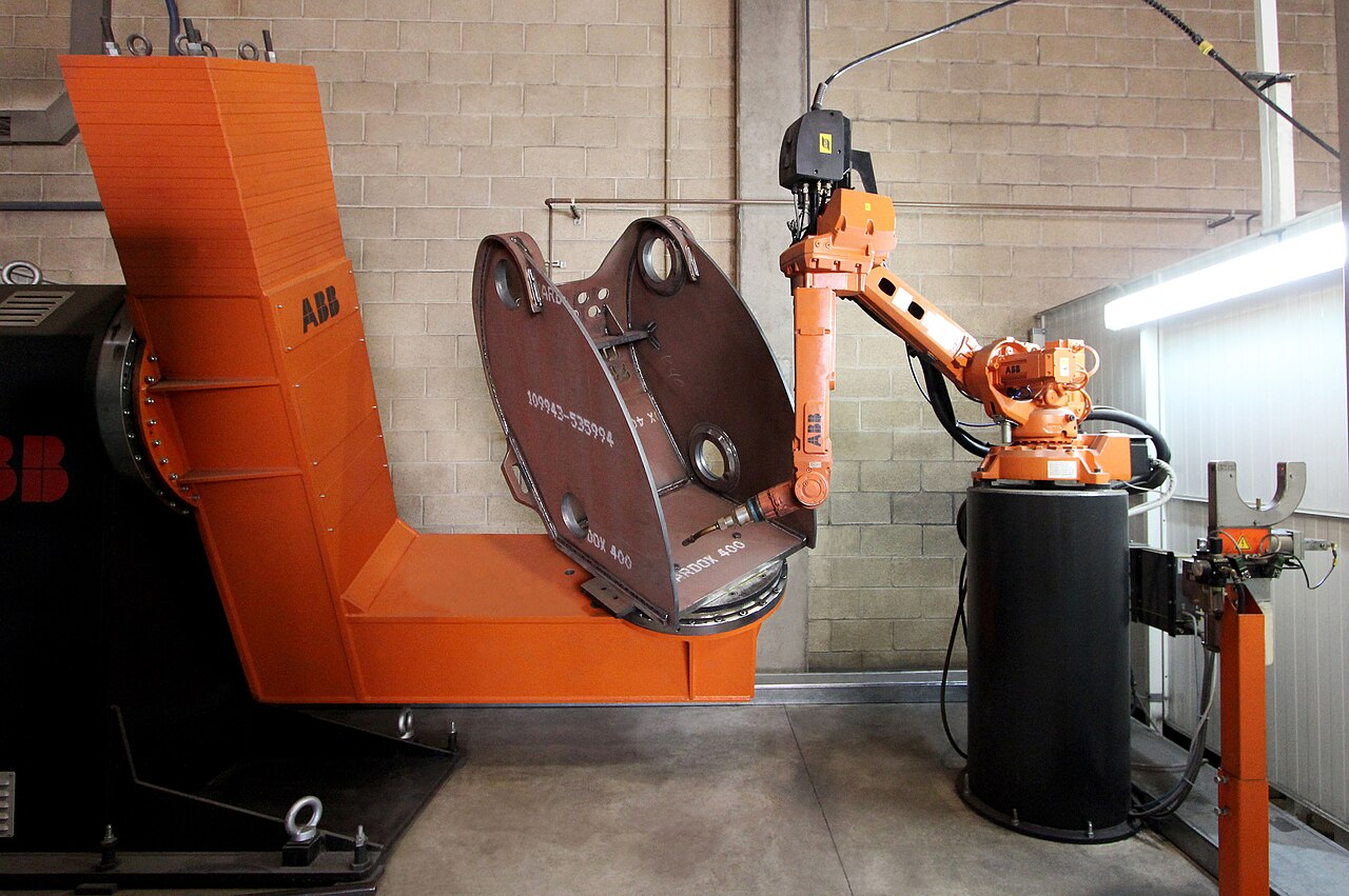
ABB welding robot and positioner holding a heavy fabricated steel housing
Robotic arc-welding cell · industry reference · Ana 2016 · CC BY-SA 4.0

Product Overview

Robotic MIG/MAG welding combines a programmed torch path with a continuously fed consumable wire electrode. It is a practical automation route for repeated frames, brackets and fabricated assemblies that require controlled filler deposition and a defined weld section.

A CHENDA robotic MIG/MAG configuration brings repeated welds into an organized cell: prepared parts locate in a fixture, the robot maintains the torch path and angle, and the welding package supplies the selected arc process. For a furniture frame, the challenge may be reaching a group of short fillets without losing alignment. For an equipment base, it may be producing the required weld section while managing heat and torch service throughout a longer cycle.

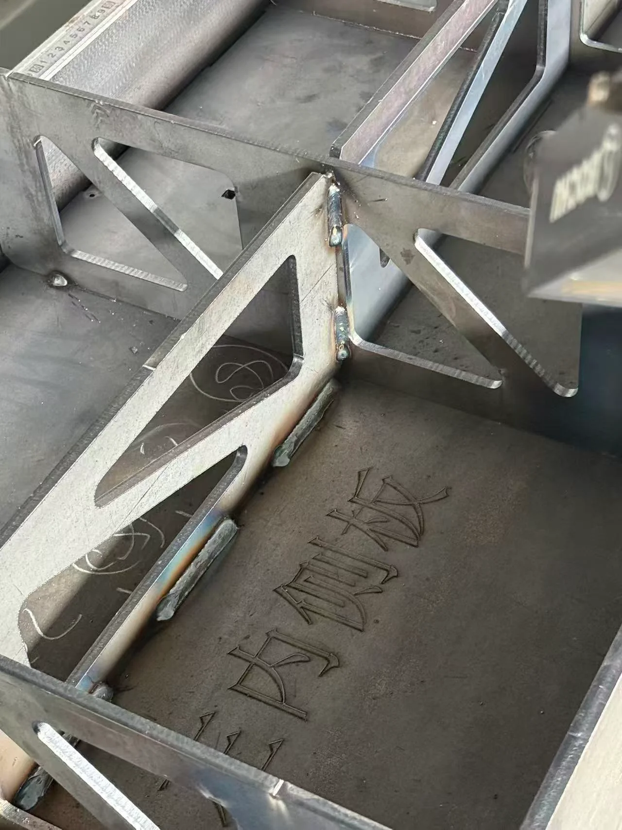
Steel assembly with triangular stiffeners and visible weld joints.
Fabricated steel joint · geometry reference

Materials & Capabilities

MIG and MAG are gas metal arc welding processes distinguished by the shielding gas. MIG uses inert gas; MAG uses active gas or mixtures containing active components. Aluminum commonly uses a suitable MIG process, while steels commonly use a MAG process with gas selected for the material and welding procedure.

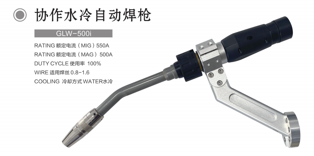
Water-cooled bent-neck MIG/MAG welding torch with original supplier labels
Arc torch geometry · supplier component reference
Workpiece requirement Process consideration Preparation priority
Steel frame with fillet welds Required weld size, arc mode and deposition Consistent fit-up, tack condition and torch access
Repeated brackets Short-weld starts, stops and sequence Stable locating and controlled heat accumulation
Stainless assembly Compatible wire, gas and heat control Surface condition and required corrosion performance
Aluminum fabrication Alloy, wire handling and appropriate gas Oxide removal and contamination control
Prepared thicker joint Pass sequence and procedure requirements Groove geometry, root conditions and interpass control

Arc welding can accommodate some joint conditions that are less suitable for a narrow laser process, but it does not accept unlimited gaps or uncontrolled preparation. Set the permissible variation through the applicable welding procedure.

Arc transfer modes change the process window

In short-circuit transfer, the wire repeatedly contacts the weld pool as metal transfers. It can serve lower-energy and thin-material tasks, but fusion and spatter still depend on the selected process. Spray transfer uses higher-current conditions and produces a more fluid pool, which affects the suitable joint orientation. Pulsed transfer alternates current levels to control droplet transfer; it requires a compatible source and the appropriate wire/gas program.

These are process families, not a list of functions included with every CHENDA configuration. The practical comparison is the result on the intended joint: acceptable fusion, bead shape, spatter and heat, at a travel speed the cell can sustain.
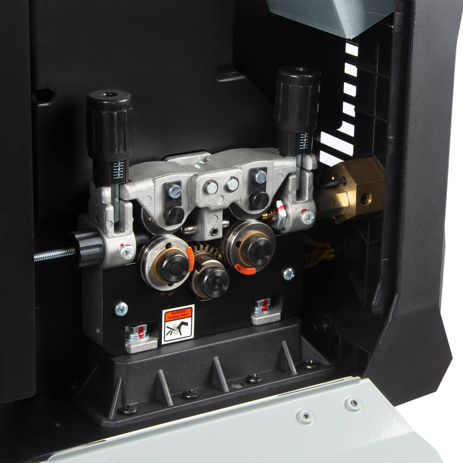
Third-party photograph of a MIG/MAG welding wire-feed mechanism with drive rolls and pressure-adjustment knobs
Arc process and wire-delivery equipment reference · PTK / ПТК welding equipment

Features & Engineering

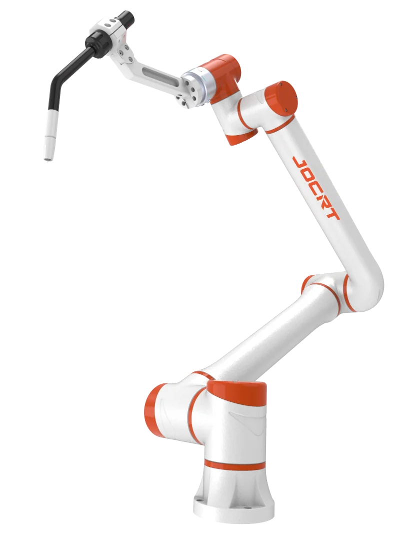
JOCRT collaborative robot arm fitted with an arc welding torch.
Arc-welding arm and torch reference
Third-party photograph of a MIG/MAG welding wire-feed mechanism with drive rolls and pressure-adjustment knobs
Keep the complete electrode-wire path controlled · PTK / ПТК welding equipment

Stable wire delivery supports a stable arc

Drive rolls, liner, contact tip and wire path must match the wire type and diameter. Excessive bends or an unsuitable liner can make delivery inconsistent. For long delivery paths or soft wire, discuss the feed architecture appropriate to the installation.

Wire-feed speed and robot travel speed perform different jobs. The feeder supplies electrode wire; robot travel distributes the deposited metal along the joint. Increasing one without considering the other changes the bead. A synergic program links selected process parameters, but still depends on the correct material, wire and gas selection. It does not remove the need to control torch position and joint preparation.

Torch geometry determines access

Torch neck angle, contact-tip position and nozzle size affect whether the robot can maintain the required work angle and contact-tip-to-work distance. Check joints near crossmembers and inside frames before accepting a layout based only on arm reach.

Contact-tip-to-work distance includes the distance from the electrical contact point toward the work; it should not be confused with the nozzle-to-part clearance. Changing that distance changes the electrical and thermal behavior of the wire and can affect current and penetration. A robot that follows the seam line while moving the torch progressively away from the joint is not preserving the same welding condition. Establish the distance for the selected procedure rather than applying one universal number.

Water-cooled bent-neck MIG/MAG welding torch with original supplier labels
Torch geometry · original supplier labels are reference data

Match thermal capacity to the real cycle

The power source and torch need adequate capacity at the intended operating conditions. A maximum current rating does not establish continuous production capability. Cooling, arc-on time, ambient conditions and pauses between welds all influence the required configuration.

For illustration, where a source defines duty cycle over a ten-minute period, a 60% rating at a stated output means six minutes at that output within the rating’s specified conditions. This is an explanation of a rating convention, not a CHENDA machine rating or permission to exceed a supplied manual. A production estimate should also consider whether the torch and cooling package support the intended duty.

ABB welding robot and positioner holding a heavy fabricated steel housing
Evaluate the complete production cycle · Ana 2016 · CC BY-SA 4.0
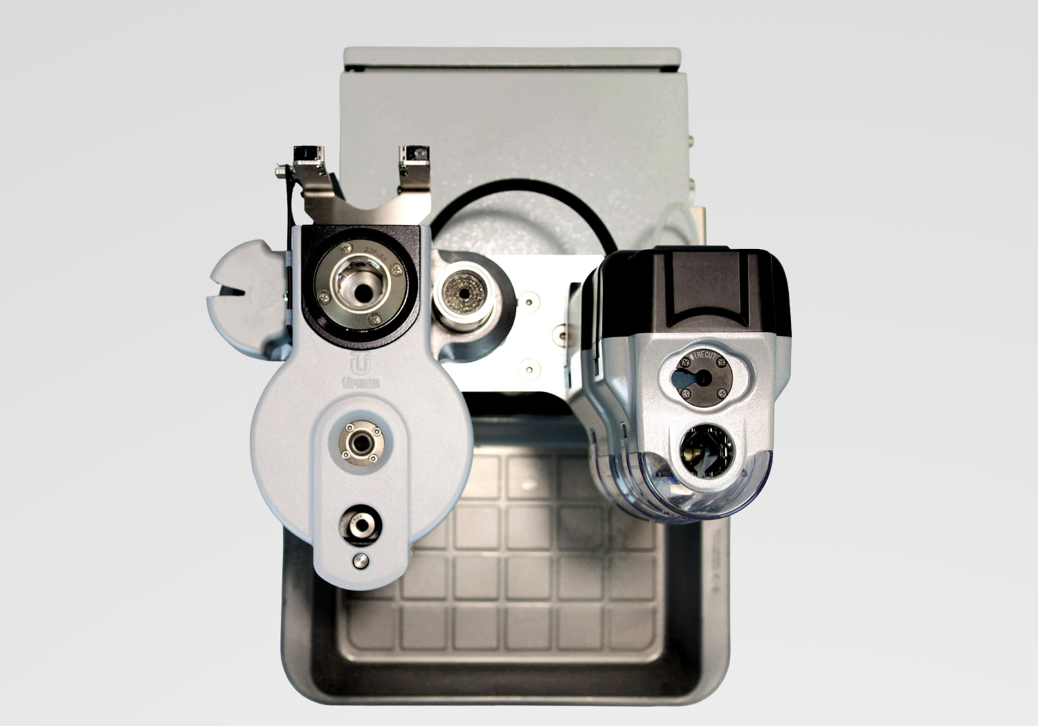
Third-party photograph of a robotic arc-welding torch maintenance station with contact-tip changing and nozzle-cleaning mechanisms
Torch service and consumable reference · Tipman

Include torch care in the production cycle

Spatter on the nozzle or a worn contact tip can disturb gas coverage and wire guidance. A suitable service routine—and torch cleaning or wire cutting equipment where justified—helps maintain the intended process between parts.

ABB welding robot and positioner holding a heavy fabricated steel housing
Robot and arc-process coordination · reference · Ana 2016 · CC BY-SA 4.0

Make welding feedback part of robot control

The robot and source exchange more than an on/off instruction. Depending on the selected interface, useful states can include source ready, arc established, process faults and selected job information. A start command without the expected response should follow defined fault handling rather than let the robot complete an unwelded path. After a stop, the system must distinguish a complete weld from a partly executed one.

Technical Specifications

Define the MIG/MAG package with arc-process ratings and consumable requirements. Laser power specifications do not apply to this equipment route.

JOCRT collaborative robot arm fitted with an arc welding torch.
Visual reference · to be replaced
Parameter Unit or format Required condition
Welding output A and V Specified arc process, supply and operating range
Rated duty cycle % at stated current and temperature Power-source rating; confirm the torch rating separately
Arc functions Available process modes Match wire, material and approved procedure
Wire electrode Classification/alloy and diameter, mm Joint metallurgy, deposition and feeder compatibility
Wire-feed range m/min Stable delivery through the installed torch package
Shielding gas Composition and flow, L/min Material, process, nozzle and working conditions
Torch cooling Gas- or water-cooled configuration Welding current, duty and access
Robot reach and tool load mm; kg and permitted moments Torch, brackets and cable package
Workpiece positioner kg, rotation and permissible moment Fixture plus workpiece and center of gravity
Electrical input V, phase, Hz and complete-system demand Power source, robot, cooling and auxiliaries

Specify fillet size, penetration or groove-weld requirements on the drawing. Parent-metal thickness alone cannot determine the necessary current, number of passes or travel speed.

For fillet welds, distinguish the specified weld dimension from the visible bead width. Extra deposited metal does not automatically add useful strength, and may increase heat or interfere with assembly. For multi-pass work, access must remain suitable as the groove fills; the first pass and later passes do not necessarily share the same torch position or program.

Samples & Demonstration

Choose a representative frame corner, bracket cluster or prepared joint. Include the least accessible weld and the normal tack arrangement. The demonstration should cover arc initiation, travel, termination and movement to the next joint.

Assess the required weld dimensions and profile, spatter, distortion and relevant inspection results. For a production trial, include torch servicing and fixture release in the cycle. A long straight demonstration weld does not establish the performance of many short welds around a crowded assembly.

Steel assembly with triangular stiffeners and visible weld joints.
Inspect the specified joint dimensions
Production symptom Factors to investigate Intended improvement
Variable bead through the same robot path Wire delivery, contact-tip condition and joint position Restore a stable process before editing motion
Defect clustered at short-weld ends Termination sequence and crater treatment Finish the required weld section consistently
Increased spatter after continued operation Nozzle/tip condition, gas coverage and process stability Sustain quality between planned service intervals
Frame moves after release Tack pattern, seam order, restraint and accumulated heat Preserve assembled dimensions after cooling

The table identifies investigation paths, not a substitute for weld inspection. Porosity or lack of fusion can remain hidden beneath an acceptable surface.

ABB welding robot and positioner holding a heavy fabricated steel housing
Robot, fixture and positioner reference · Ana 2016 · CC BY-SA 4.0

Configuration & Options

Discuss the robot, arc power source, wire feeder, torch, cooling, gas equipment and control interface together. The welding return path should be designed for the cell; do not assume robot bearings or moving mechanical connections provide an acceptable current path.

Options may include a workpiece positioner, additional stations, torch cleaning, wire cutting, seam finding or tracking, and welding-data interfaces. Confirm compatibility with the selected arc process. A pulse-capable power source does not automatically include every specialized process, sensor or robot communication function.

Applications & Workflow

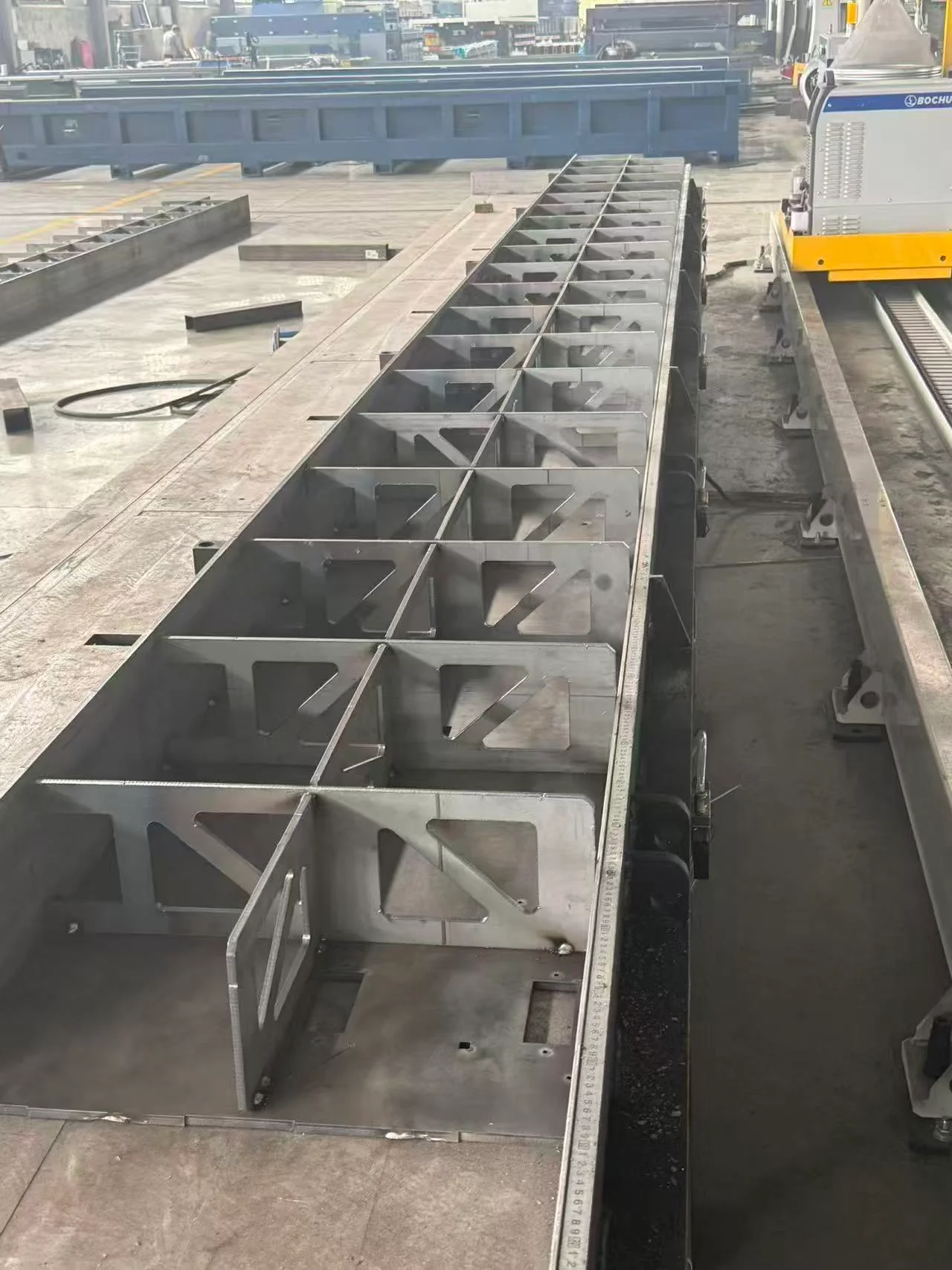
Long steel beam assembly with repeated stiffeners beside a BOCHU rail-mounted system.
Long fabricated member · workflow reference

Robotic MIG/MAG is relevant to repeated tube frames, equipment bases, brackets and other assemblies with accessible arc-welded joints. Prepare components, establish datums, tack where required and clamp before the robot cycle. Plan the seam order so the developing heat and contraction do not pull critical dimensions outside tolerance.

Positioners can improve access and present joints in favorable orientations. Their benefit should be weighed against indexing time, fixture complexity and part handling. After welding, release and inspect the assembly before further machining, coating or installation.

For a rectangular tube frame with several brackets, a useful sequence separates locating from joining: establish the frame dimensions, retain each bracket at its drawing datum, then arrange welds so the torch can enter without being blocked by earlier assembly steps. A positioner may turn the frame to improve access rather than asking the robot to maintain an awkward overhead approach. The production benefit comes from repeatable access and geometry, not merely removing the operator’s hand from the torch.

Installation & Support

Prepare the electrical supply, gas storage and delivery, fume extraction, robot support and workpiece handling. Protect surrounding people from arc radiation and spatter, and control access to robot and positioner movement. A collaborative arm does not remove these process hazards.

Training should cover torch-center calibration, wire and gas changes, consumable inspection, program selection, weld-sequence recovery and maintenance of the return-current connection. Confirm the spare tips, nozzles, liners and other consumables matched to the supplied torch.

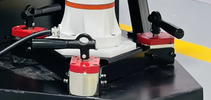
Robot base secured by a triangular bracket with three lever-operated magnetic mounts.
Robot support and installation interface · reference

Technical Resources

Keep the arc-source specification, installed process functions, torch configuration and robot interface identified in the equipment record. The application record should connect the wire, gas and weld procedure with the accepted assembly. A replacement source or torch must be evaluated against that combination, not only against the largest current number on the cabinet.

Review CHENDA Quality Control for configuration and sample acceptance, and plan production handover around the cell layout, approved programs and consumables. Provide the weld drawing and applicable inspection requirements when discussing a trial.

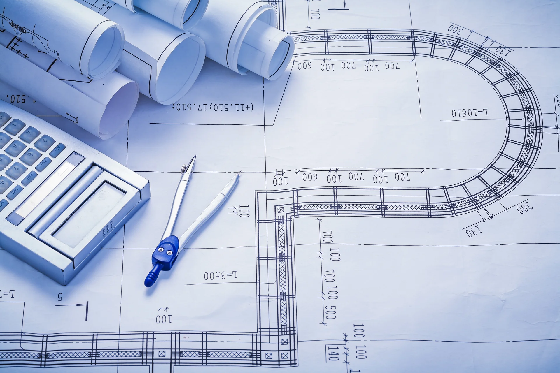
Technical drawings with a calculator and drafting compass
Procedure and weld-drawing review

Product FAQs

Steel assembly with triangular stiffeners and visible weld joints.
Joint geometry reference
Water-cooled bent-neck MIG/MAG welding torch with original supplier labels
Shielded arc-torch reference

What is the difference between MIG and MAG?

The distinction is the shielding gas: inert for MIG, active or partly active for MAG. Material and procedure determine the gas choice. Changing from steel to aluminum involves more than loading a different robot program.

Steel assembly with triangular stiffeners and visible weld joints.
Visual reference · to be replaced

Does a larger current rating mean a stronger weld?

No. Strength depends on the required weld geometry, material compatibility and process quality. Excessive current or heat can create other defects or distortion. Select the equipment around an appropriate procedure.

ABB welding robot and positioner holding a heavy fabricated steel housing
Complete-cell duty reference · Ana 2016 · CC BY-SA 4.0

Why does duty cycle matter in a robot cell?

A robot may maintain arc-on time more consistently than manual work. The power source and torch must support that duty at the required output and temperature; intermittent maximum ratings should not be mistaken for continuous ratings.

Third-party photograph of a MIG/MAG welding wire-feed mechanism with drive rolls and pressure-adjustment knobs
Wire delivery reference · PTK / ПТК welding equipment

Can the cell use the same wire system for steel and aluminum?

Possibly with compatible equipment and the necessary changes, but soft aluminum wire has different feeding requirements. Review drive components, liner, torch and delivery length as a complete path.

Long steel beam assembly with repeated stiffeners beside a BOCHU rail-mounted system.
Visual reference · to be replaced

Can seam tracking compensate for poor fabrication?

It can address defined variations when a compatible system is fitted and validated. It does not automatically correct missing material, incorrect joint preparation, excessive gaps or a badly distorted assembly.

Third-party photograph of a robotic arc-welding torch maintenance station with contact-tip changing and nozzle-cleaning mechanisms
Torch consumable reference · Tipman

Why include nozzle cleaning in a cycle estimate?

Consumable condition affects gas coverage and wire guidance. Ignoring necessary servicing can make a cycle estimate look attractive while understating the work needed to sustain acceptable welds.

Request a Quote

Send the assembly drawing, material grade, joint preparation and required weld size. Include part and fixture weight, expected gap variation, current wire and gas if known, and your production target. Mark any seams that require special inspection or have restricted torch access.

Steel assembly with triangular stiffeners and visible weld joints.
Specify the weld size and access constraints