Laser joining / Robotic motion

Robotic Laser Welding Systems

Product Overview

Robotic laser welding brings a focused welding process to assemblies with changing seam directions and tool angles. A robot presents the laser head to each joint while the fixture maintains the part geometry. This combination is worth evaluating for repeated enclosures, formed sheet-metal assemblies and other components where access extends beyond a simple platform path.

A CHENDA robotic laser welding configuration brings the joining process to the faces of the assembly that need it. For an enclosure, that may mean changing from a horizontal seam to an upright corner while preserving the beam’s relationship to the joint. For a formed housing, it may mean following a curved path without interrupting the seam for manual repositioning. Stable fit-up and a carefully arranged cell turn this freedom of motion into useful production capability.

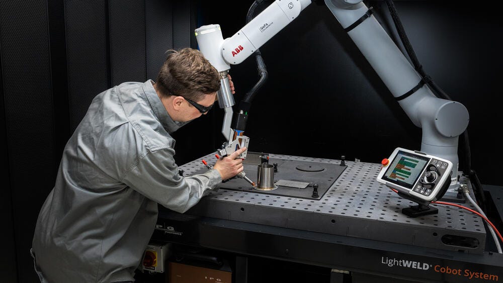
Operator teaching an IPG LightWELD laser-welding cobot path on a fixture table
Laser welding path teaching · industry reference · IPG Photonics

Materials & Capabilities

Steel, stainless steel and selected aluminum alloys can be considered after reviewing grade, thickness, surface condition and joint design. Laser welding can concentrate heat in a narrow region, but the achievable weld section and distortion depend on the complete process.

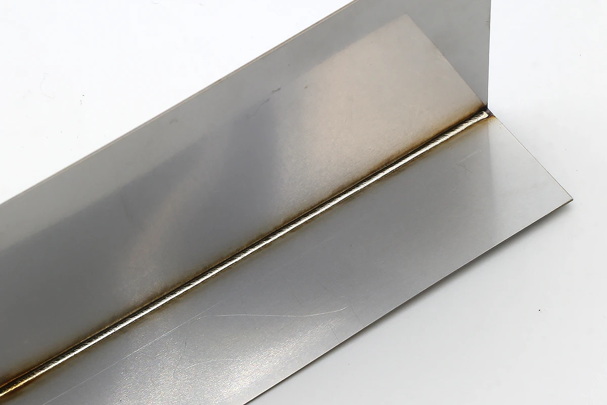
Third-party laser-welded sheet-metal inside-corner sample with a continuous visible weld seam
Laser-welded corner · sample reference · smartDIYs
Joint situation Robotic laser opportunity Main constraint
Several enclosure corners Change head orientation between seams Head clearance and consistent corner fit-up
Curved or spatial seam Follow a programmed three-dimensional path Tool angle, focal relationship and part repeatability
Repeated visible sheet joint Control energy delivery along the seam Surface preparation, bead shape and heat discoloration
Joint requiring added metal Coordinate a compatible wire feeder Wire approach, alloy and stable delivery
Seams on different sides Combine robot movement with repositioning where needed Fixture access, containment and loading sequence

Surface joining and deeper penetration have different objectives

In heat-conduction laser welding, energy enters near the surface and spreads into the joint. This can serve thin-wall and visible-edge applications where the required section is compatible with that process. Deep-penetration welding uses a vapor cavity, often called a keyhole, to carry energy farther into the material. The resulting weld geometry is different.

These are process behaviors, not interchangeable labels for every robot laser. Source, optics, energy density, travel and material determine the operating condition. A wider visible bead does not by itself indicate a deeper joint, and a narrow seam is not proof that the required interface has fused.

Do not select a system solely from the thickest plate in the workshop. A thin enclosure with difficult access or a tight appearance requirement can demand more application development than a simple thicker coupon.
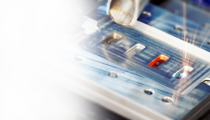
Laser welding electrical contacts held in a machined fixture
Local laser interaction at a held joint · process reference · AMADA WELD TECH

Features & Engineering

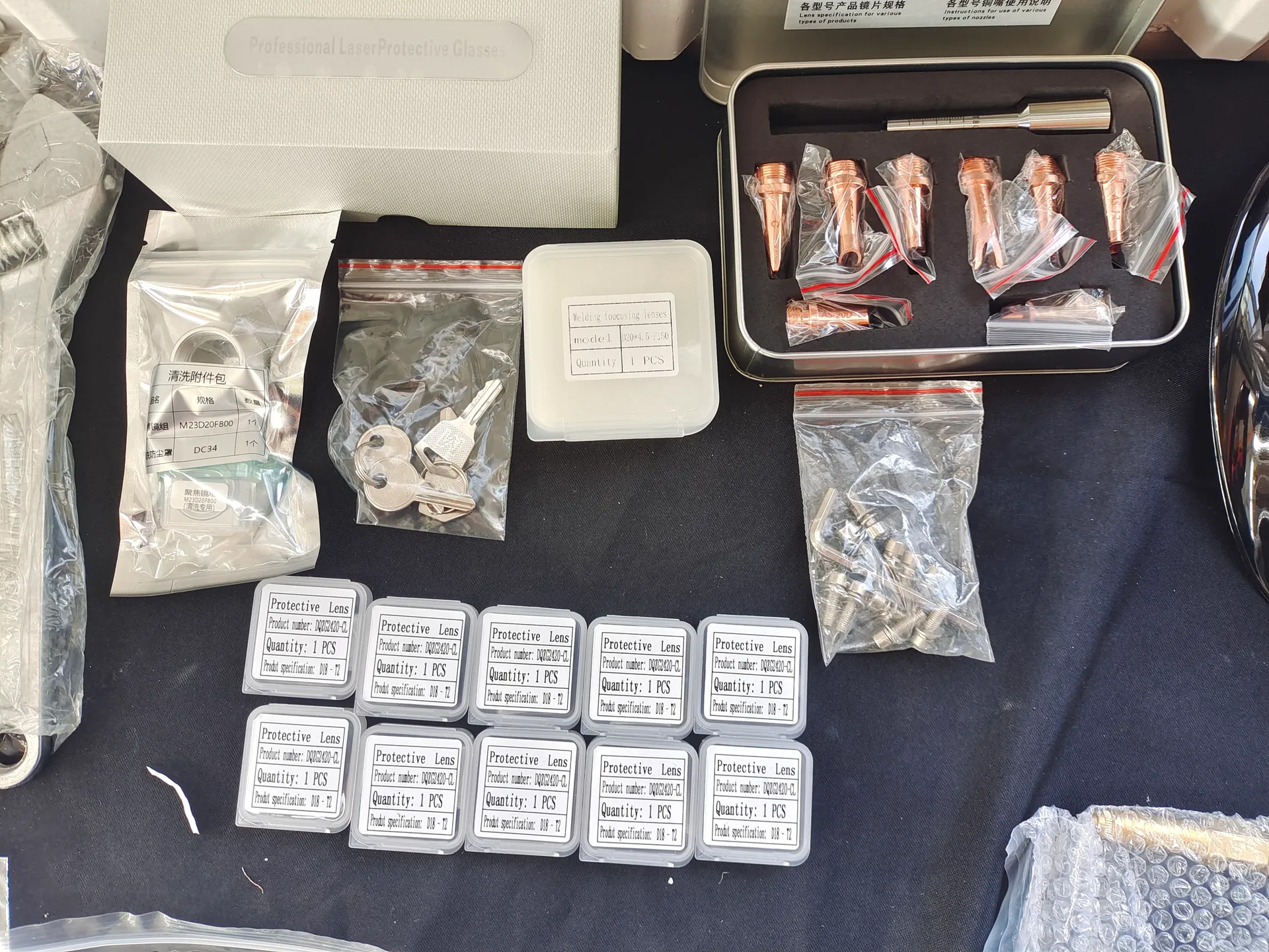
Copper welding nozzles, packaged protective optics and accessories arranged on a work surface.
Optical and nozzle consumables · reference
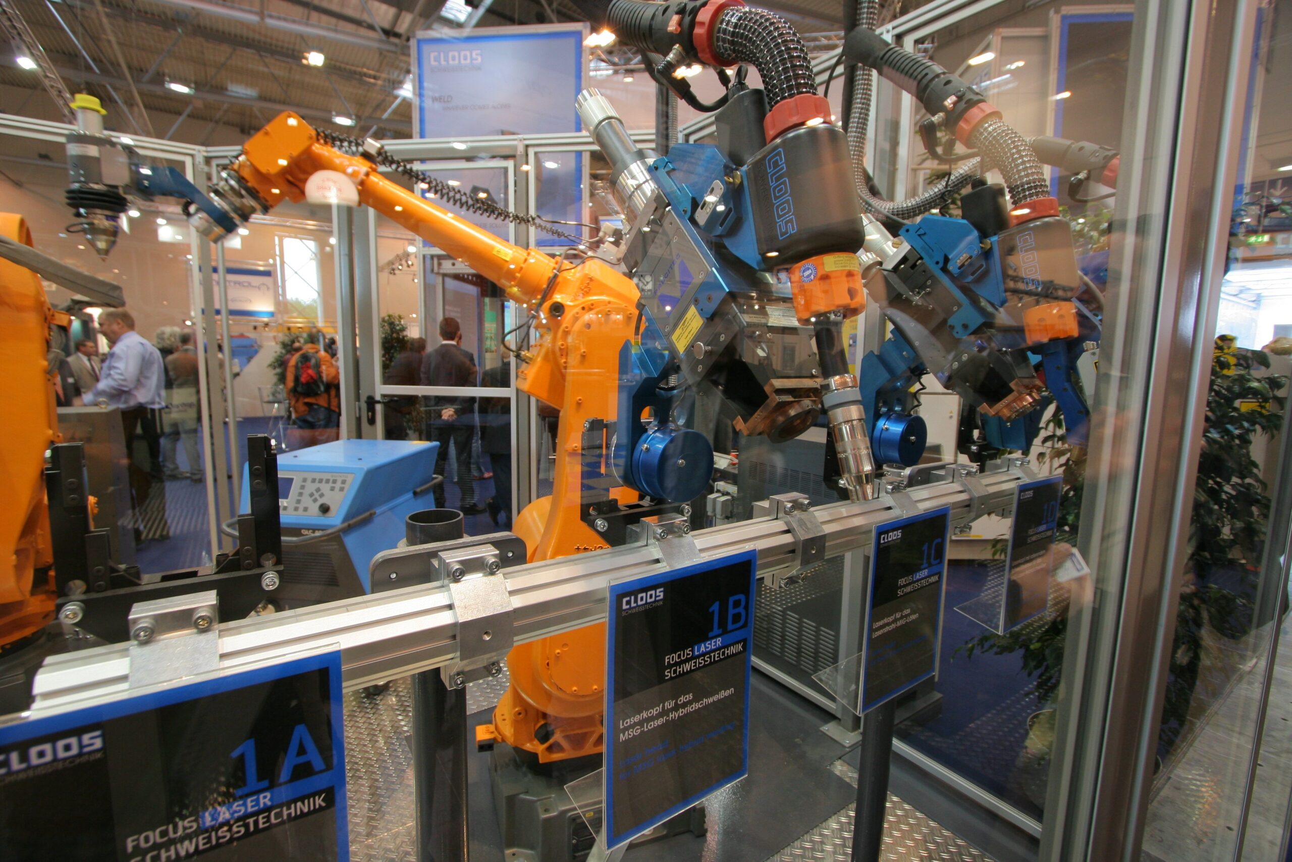
CLOOS laser welding heads and robots at the Essen welding exhibition
Robot-mounted laser tooling · equipment reference · Pipimaru · CC BY-SA 3.0

Control the beam-to-joint relationship

The working distance and head orientation must remain suitable along the seam. A robot’s repeatable path is useful only when the joint returns to the intended location. Establish datums and control upstream cut and bend variation before relying on a stored program.

The robot’s tool reference and the optical working point need to agree. A head can travel along the correct visible line while its focal relationship to the surface changes. Head mounting, tool calibration and fixture references should therefore be treated together. After head service, verify the relevant references before compensating with a new welding path.

Design the fixture around optical and mechanical access

Clamps should hold the seam without obstructing the head or wire. Their surfaces and positions also form part of the laser exposure assessment. Evaluate the beam path and potential transmission beyond the joint, not only whether the robot can physically pass through the space.

On a box-shaped assembly, the last accessible corner can be harder to hold than the first. Closing the structure may remove access for an internal support or alter how the component sits in the fixture. The welding sequence and locating strategy should preserve the required gap until the final seam, rather than rely on the first welded edges to pull the remainder into position.

Real laser welding of a clamped component in a fixed tooling assembly
Clamping and optical access · process reference · AMADA WELD TECH

Match the head, source and wire system

Beam oscillation, focal geometry and optional filler delivery influence the weld profile. A wire feeder adds a physical approach direction that the robot must preserve. Test starts, corners and seam ends where motion or wire behavior can differ from a long straight run.

A wire nozzle that works on one face may point away from the molten region after the head turns to another face. Reviewing the tool’s orientation along the path reveals this before it becomes an intermittent feeding problem. Filler delivery must also follow changes in travel: a seam-end slowdown with unchanged feeding can increase local buildup. The appropriate response depends on the controller and validated process, not simply increasing the laser rating.

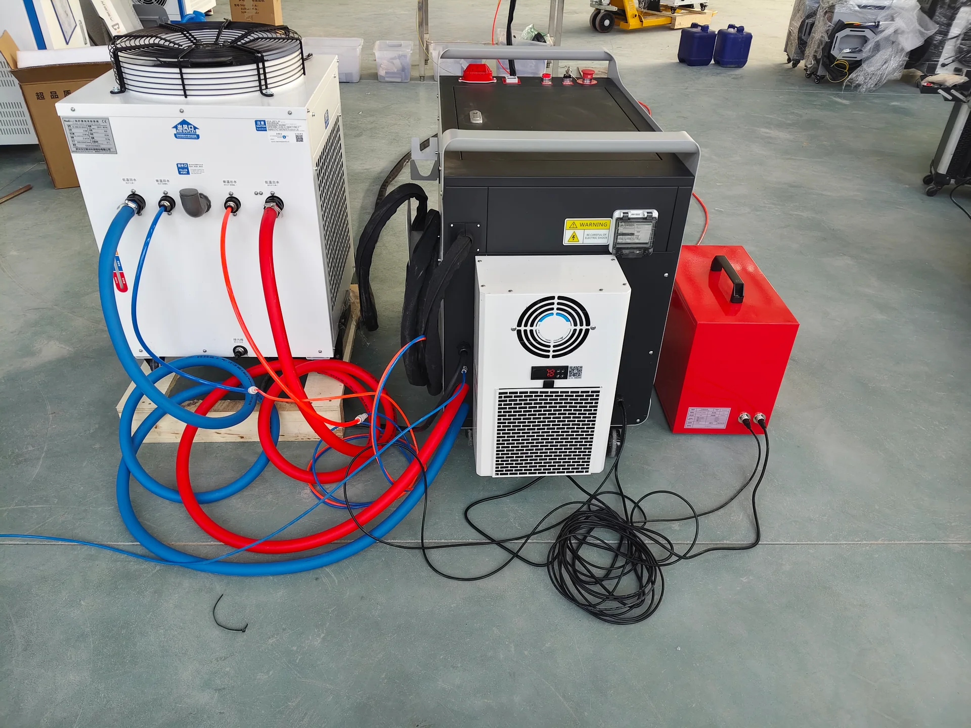
Rear view of a laser welding cabinet and chiller with connected cooling hoses and cables.
Cooling circuit connections
Copper welding nozzles, packaged protective optics and accessories arranged on a work surface.
Protective optics

Protect process consistency through cooling and optics care

The source and processing head need the specified thermal conditions. Protective optics require an appropriate inspection and replacement routine. Contamination, damaged optics or unstable cooling can change the process even when the robot program has not changed.

This matters when diagnosing gradual drift. If a previously acceptable seam changes across several fixtures or programs, inspect shared process conditions before editing every path. If only one location changes, part access, local fit-up or orientation may deserve attention first. The pattern of the variation helps separate a cell-wide process issue from one joint’s geometry.

Technical Specifications

The selected laser package and robot define the equipment ratings. The joint and fixture define the useful operating window.

CLOOS laser welding heads and robots at the Essen welding exhibition
Tool-package reference · Pipimaru · CC BY-SA 3.0
Specification Unit or description Application condition
Laser source output W Approved material, weld geometry and travel speed
Processing head Optical configuration; supported output Matched to source, focal geometry and intended beam movement
Beam movement Pattern and width, mm where supported Required weld width and tested energy distribution
Robot reach mm with envelope drawing Actual head pose and fixture clearance
Tool payload kg and allowed moments Head, mount, wire attachment and supported services
Robot repeatability mm under stated conditions Separate from seam-location and finished-part tolerance
Filler system Alloy; diameter, mm; feed, m/min Joint metallurgy, reinforcement and head compatibility
Cooling System type and service requirements Source/head demands and installation environment
Workpiece capacity Envelope in mm; mass in kg Fixture, robot access and any positioner limits
Cell output s per accepted assembly Loading, clamping, welding, repositioning and unloading

Robot precision and laser power do not independently guarantee penetration. A process trial must connect these ratings with the actual joint, focal position, travel speed and surface preparation.

Samples & Demonstration

For a useful trial, include the least accessible seam and a visible seam on the same representative assembly. Load the part into a realistic fixture and demonstrate the transitions between welds. Where filler is required, retain the intended wire approach throughout the path.

Review the seam face, penetration evidence appropriate to the application and dimensions after the part cools and is released. Include normal production variation in a repeat trial. For a sealing requirement, agree on a relevant leak test rather than judging only the external bead.

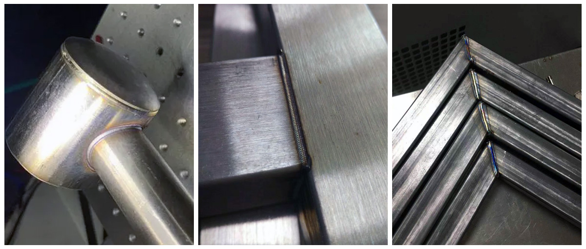
Third-party handheld-laser-welding samples showing a round-tube connection, a rectangular joint and welded mitered tube-frame corners
Joint transitions · laser-welded sample references · Suntop Laser

Evaluate the seam where the process changes

Third-party laser-welded sheet-metal inside-corner sample with a continuous visible weld seam
Corner-seam reference · smartDIYs
Location What changes Useful evidence
Start and termination Source, motion and optional wire transition Continuity and local bead/section condition
Tight contour or corner Travel direction and possible speed reduction Local heating, contour position and weld geometry
Change between faces Head angle and wire approach Stable access, focal relationship and delivery
Area close to a clamp Mechanical clearance and local restraint Unobstructed processing and dimensions after release

If internal soundness matters, the chosen inspection must address it. A stable video of robot motion or a clean-looking surface is useful evidence of only part of the process.

Configuration & Options

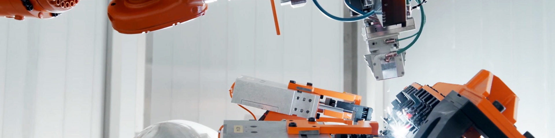
Industrial robot laser welding an automotive door assembly inside a white enclosed workcell
Laser process, robot and enclosure · integrated-cell reference · Precitec

Discuss the robot, laser source, head, cooling, control interface and laser-protective cell as an integrated configuration. A fixed fixture may be sufficient for accessible assemblies; a positioner may improve access to additional faces.

Optional wire feeding, process viewing, seam-location sensing and production-data functions should follow the application. Confirm the exact sensing purpose and limitations. Observing a seam with a camera is different from automatically locating it, following it during welding or verifying its internal quality.

Cell controls also need to connect source readiness, cooling state, extraction and access protection to the intended operating sequence. The available feedback differs by equipment. A laser command should not be treated as evidence that the required process condition existed throughout the seam; interruptions must leave the assembly in an identifiable state for assessment.

Applications & Workflow

Repeated cabinets, housings, metal furniture components and formed sheet assemblies are relevant application directions. Good preparation starts before welding: accurate blanks, controlled bending and clean joining surfaces reduce the variation the cell must handle.

Load the parts to the intended datums, clamp without blocking the path, confirm the correct program and execute the seam sequence. Where several faces are welded, plan the order to preserve access and manage heat. Inspect the released assembly before it moves to finishing, coating or final assembly.

For a visible stainless housing, a sensible development goal is a stable finished shape with a seam compatible with the required surface treatment. That goal may favor a different joint detail from one chosen purely for easy manual fit-up. Tabs, formed edges or locating features can help assembly, but their effect on beam access and the visible seam belongs in the joint review. Improving the upstream part design can make the welding cell simpler to run.

Painted metal filing cabinets with open drawers
Cabinet and housing application reference

Installation & Support

Industrial robot laser welding an automotive door assembly inside a white enclosed workcell
Contained laser-welding work area · reference · Precitec

The cell layout must address laser exposure, reflected and transmitted beams, robot movement, extraction and maintenance access. A collaborative arm does not make an exposed laser process suitable for unrestricted shared working space. Protection is determined for the full application and its operating modes.

Training should include tool and frame calibration, fixture loading, process setup, optics care and recovery after an interrupted seam. Preserve approved robot programs and welding parameters together so a later change can be traced to the correct setup.

Technical Resources

The useful technical record links head geometry and optical configuration to the robot tool reference, fixture and joint. Include the selected gas and filler arrangement where applicable, and retain sample evidence for the seam characteristics that matter to the assembly.

Review CHENDA Quality Control for the connection between configuration identification, functional checks and sample acceptance. The installation and training plan should use the same cell layout and approved setup information used to prepare the equipment.

Technical drawings with a calculator and drafting compass
Tool reference, fixture and joint review

Product FAQs

Third-party laser-welded sheet-metal inside-corner sample with a continuous visible weld seam
Joint quality reference · smartDIYs
Operator teaching an IPG LightWELD laser-welding cobot path on a fixture table
Tool-path teaching reference · IPG Photonics

Is robot repeatability the same as weld accuracy?

No. It describes a robot performance characteristic under defined conditions. Actual seam position also depends on calibration, part variation, fixture location, head geometry and thermal movement.

CLOOS laser welding heads and robots at the Essen welding exhibition
Laser tool geometry · Pipimaru · CC BY-SA 3.0

Can the robot weld around every side without repositioning?

Only if the tool can reach every seam with the required orientation and clearance. An obstructed seam may require a different fixture, part orientation or positioner even when it lies inside the arm’s nominal radius.

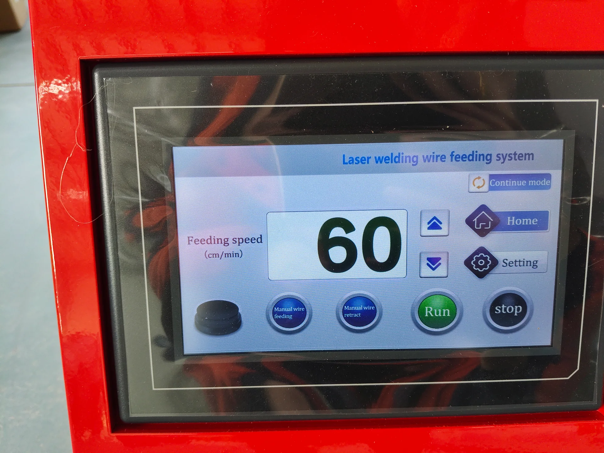
Touchscreen on a red laser welding wire feeder showing feeding controls.

Is laser welding always performed without wire?

No. Some joints use the base material alone; others need compatible filler for metallurgy, reinforcement or a validated fit-up condition. The feeder and head arrangement must be included in the motion review.

Real laser welding of a clamped component in a fixed tooling assembly
Located joint reference · AMADA WELD TECH

Will the robot find the seam automatically?

Only if a suitable sensing function is specified, integrated and demonstrated. A basic programmed path follows its taught coordinates. Good fixtures and consistent parts remain fundamental.

Third-party handheld-laser-welding samples showing a round-tube connection, a rectangular joint and welded mitered tube-frame corners
Assembled-joint reference · Suntop Laser

Does a narrow laser seam mean there is no distortion?

No. Concentrated energy can help control heat input, but restraint, seam sequence, material and assembly geometry still affect movement. Evaluate the cooled, unclamped part.

Request a Quote

Send the assembly model, seam map, material grade, thicknesses and acceptable joint variation. Identify visible surfaces, the required weld section and any sealing requirement. Add the intended fixture, normal batch size, cycle target and available installation space.

Third-party laser-welded sheet-metal inside-corner sample with a continuous visible weld seam
Define the finished seam requirement · smartDIYs