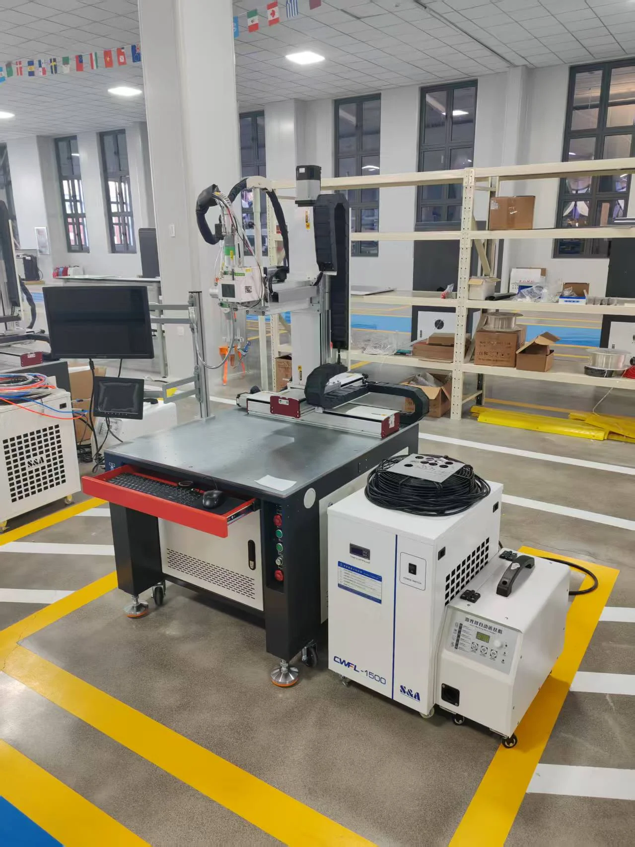
The complete welding cell

Robotic Welding Systems

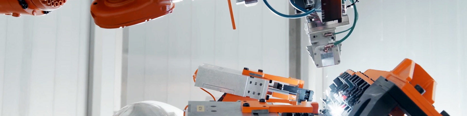
Industrial robot laser welding an automotive door assembly inside a white enclosed workcell
Robotic laser welding in a contained cell · industry reference · Precitec

Product Overview

A robotic welding system carries the welding tool along a programmed path while controlling its orientation around the workpiece. Its value is strongest where repeatable assemblies contain several seams, changing approach angles or handling steps that can be organized into a consistent cell cycle.

CHENDA’s robotic welding range separates two process routes: robotic laser welding for suitable joints using concentrated optical energy, and robotic MIG/MAG welding for arc welding with a continuously fed wire electrode. An enclosure corner and a frame fillet can share a robot-style movement without sharing the same joining requirements. The complete cell follows the process and assembly.

Materials & Capabilities

Steel, stainless steel and selected aluminum alloys are evaluated with different process settings, consumables and preparation. The same material may favor a laser process on one joint and an arc process on another.

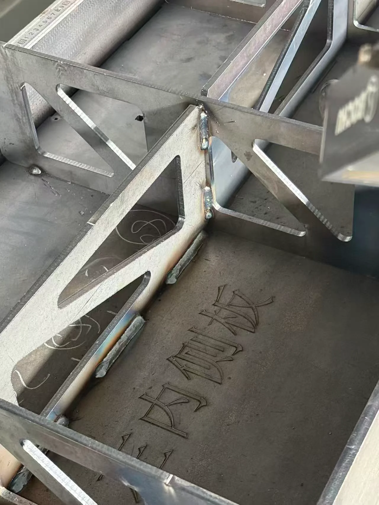
Steel assembly with triangular stiffeners and visible weld joints.
Joint geometry · fabricated-assembly reference
Production need Laser route MIG/MAG route
Visible sheet-metal seam Evaluate concentrated energy and bead appearance Evaluate heat, bead profile and finishing requirement
Controlled close-fitting joint A strong candidate for process testing Select arc mode and filler appropriate to the joint
Fabricated frame with specified fillets Verify whether the required weld section is practical Evaluate deposition, access and weld procedure
Multiple faces or changing seam angles Check head, beam and wire access Check torch angle, stickout and gas coverage
Variable part position Improve locating; assess any configured sensing Improve locating; assess any configured sensing

Automation requires a repeatable relationship between the seam and tool. Warped parts, inconsistent tack welds or accumulated bending error should be addressed in the production process and fixture design.

Features & Engineering

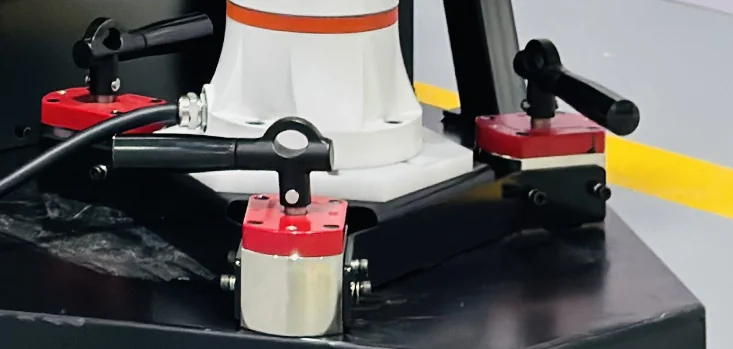
Robot base secured by a triangular bracket with three lever-operated magnetic mounts.
Robot mounting arrangement · reference

Reach is a three-dimensional problem

A nominal reach radius does not show whether the robot can hold the required tool angle at every point. The head or torch, cable package, clamps and part geometry may restrict access. Evaluate approaches and transitions as well as the welding path itself.

A seam near the edge of the working envelope can force an awkward arm posture even if the tool reaches its endpoints. During the connecting path, individual joints may approach movement limits or require rapid changes. Moving the fixture or changing the part orientation can be more effective than adding reach without reviewing the actual path. Cable clearance must also remain usable through the full movement, including the return to the loading position.
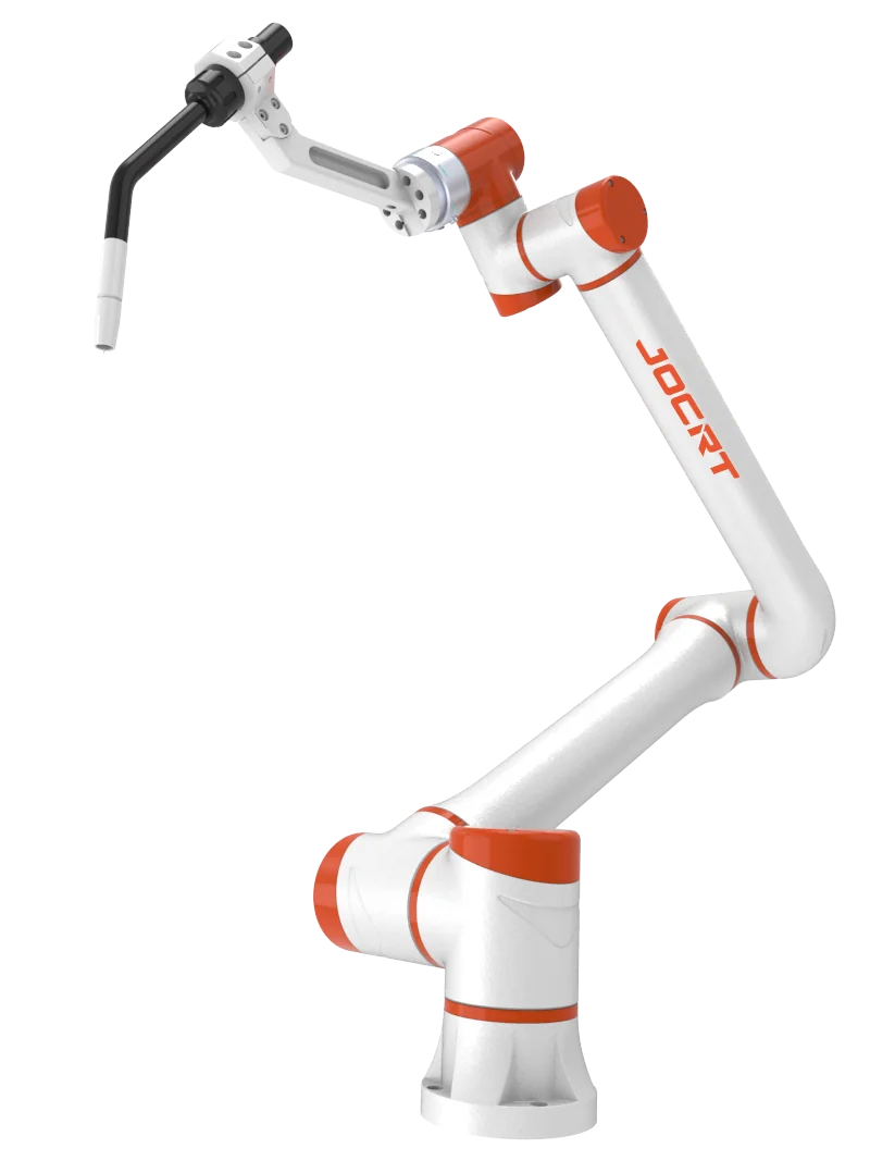
JOCRT collaborative robot arm fitted with an arc welding torch.
Arm and torch geometry · arc-welding reference
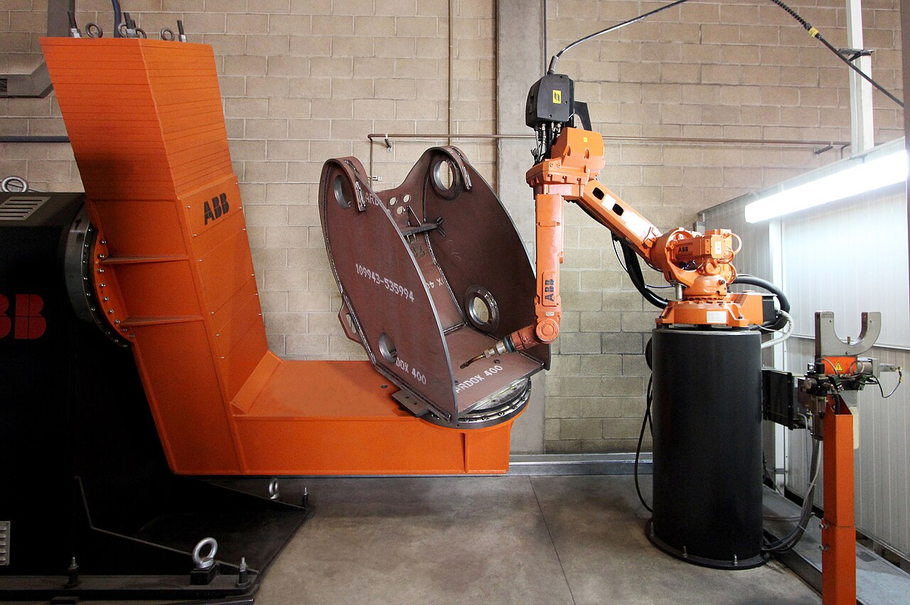
ABB welding robot and positioner holding a heavy fabricated steel housing
Robot, fixture and positioner · arc-welding reference · Ana 2016 · CC BY-SA 4.0

Fixtures turn incoming parts into a stable process

Good locating establishes datums without hiding the seam. Clamp placement must resist movement while allowing loading and inspection. A positioner can present additional faces, but its load capacity must account for the workpiece and fixture, including their center of gravity.

Keep tool calibration separate from part location

The tool center point, or TCP, describes the working point and orientation of the tool relative to the robot flange. The part coordinate system describes where the fixture or assembly sits. These references solve different problems. If a torch neck moves after a collision, changing the fixture coordinates to make one seam look correct can leave other orientations wrong. Restore and check the tool reference before altering the part program.

A fixture moved to another location similarly needs its location re-established. A robot can accurately repeat an outdated coordinate system. Repeatability is valuable after the physical references are correct; it cannot identify which reference changed.

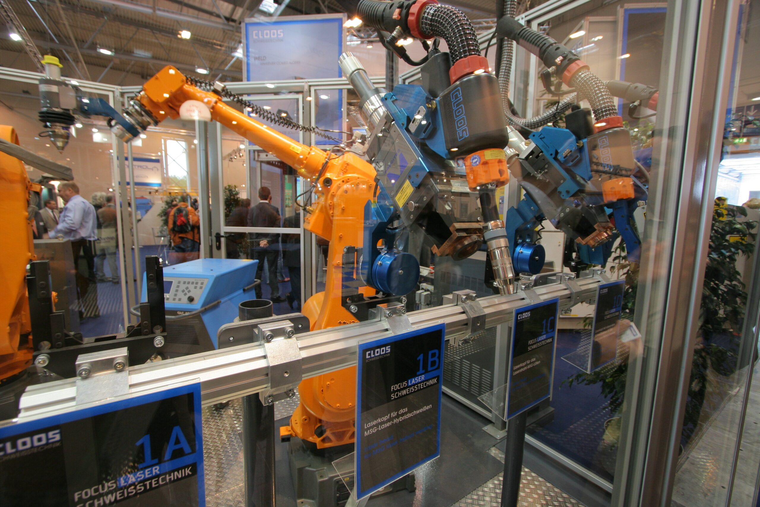
CLOOS laser welding heads and robots at the Essen welding exhibition
Laser tool and flange geometry · equipment reference · Pipimaru · CC BY-SA 3.0

Process equipment must communicate with motion

Industrial robot laser welding an automotive door assembly inside a white enclosed workcell
Motion and process equipment form one cell · Precitec

Laser output or arc settings, wire feeding, shielding gas and cooling must operate in the correct sequence with the robot. A useful interface distinguishes equipment readiness, a start command, active-process feedback and faults. In an arc cell, for example, commanding welding does not establish that an arc has formed. The available signals and response logic depend on the selected source and interface.

Stopped cycles need a defined part state: not started, partly welded, completed or awaiting inspection. That distinction supports recovery without silently treating a partially joined assembly as a finished part. It also helps separate a communication fault from a material or joint problem.

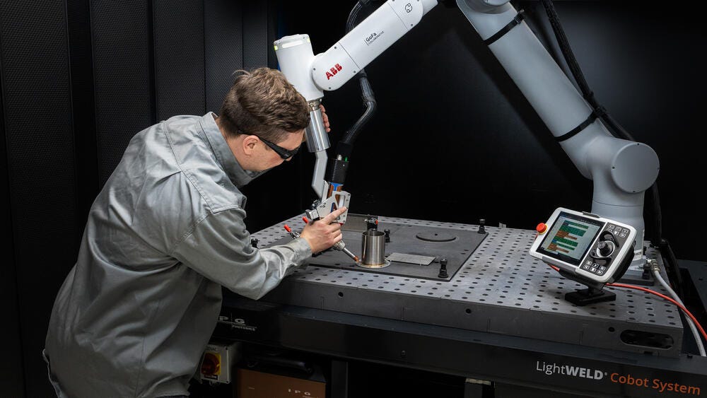
Operator teaching an IPG LightWELD laser-welding cobot path on a fixture table
Laser welding path teaching · reference · IPG Photonics

Programming convenience does not replace cell design

Teach-pendant programming, guided teaching or offline methods may be available according to the robot and software selected. Their usefulness depends on seam complexity and batch variation. A collaborative robot arm still requires a cell assessment covering the welding process, motion and workpiece hazards.

Technical Specifications

Use the following comparison to prepare a meaningful robot-cell specification. Exact ratings and operating conditions are provided for the selected configuration.

JOCRT collaborative robot arm fitted with an arc welding torch.
Visual reference · to be replaced
Field Unit or definition Why it matters
Robot reach mm, with working-envelope drawing Accessible seam positions at the required tool orientation
Tool payload kg and permitted load moments Head/torch, brackets, sensors and supported cable loads
Robot repeatability mm under stated test conditions One contributor to path consistency, not a weld tolerance
Positioner capacity kg; permissible moment and rotation Combined fixture and part loading
Laser process rating Optical output, W Laser route only; relate to the tested joint
Arc process rating A, V and duty cycle at stated conditions MIG/MAG route only; relate to the chosen process
Wire system Alloy; diameter, mm; feed range, m/min Stable filler delivery and access
Cell size Length × width × height, mm Guarding, access, handling and maintenance space
Production capacity s per assembly; product mix Welding plus loading, indexing, inspection and service tasks

The robot’s free-motion speed is not a welding production rate. Likewise, repeatability cannot compensate for an incorrectly calibrated tool or a fixture that locates parts differently from cycle to cycle.

Compare usable cell capacity

Tool load includes more than the head or torch mass. Mounts, sensors and supported services contribute weight and moment about the wrist. A long offset can be important even when the total mass appears modest. Positioner loading likewise depends on the combined fixture and part, not the part alone.

Indexing and coordinated rotation also describe different capacities. An indexing positioner stops at selected orientations before welding. Coordinated motion allows the robot and external axis to move together relative to the part. The latter requires a compatible control arrangement and suitable calibration; it is not established merely by including a rotary table.

ABB welding robot and positioner holding a heavy fabricated steel housing
Combined part and fixture loading reference · Ana 2016 · CC BY-SA 4.0
Steel assembly with triangular stiffeners and visible weld joints.
Review the complete joint and assembly

Samples & Demonstration

Demonstrate a complete assembly with representative clamps and tool angles. Include short seams, obstructed locations and the transition between faces. A single open flat coupon cannot establish full robot-cell coverage.

Repeat the load–weld–unload sequence to evaluate the complete cycle. Check how the system handles normal component variation, consumable servicing and recovery from a stopped cycle. Review the cooled assembly against its weld and dimensional criteria.

Useful evidence distinguishes geometry from process. A dry movement establishes clearance and tool orientation; an actual weld establishes what happens under heat, gas flow and wire delivery. Repeated loading establishes whether the fixture returns the seam to the same place. These observations answer different questions and are most useful when tied to the same assembly revision.

Configuration & Options

A robot cell can include a fixed table, rotary positioner or multiple work stations, depending on part access and loading time. Options to discuss include fixture confirmation, seam-location sensing, process viewing, torch service equipment and production-data exchange.

Specify the function of each proposed option. Seam finding locates a feature before welding; seam tracking follows variation during the path; process monitoring observes selected signals. These are different functions and should not be combined under a vague promise of automatic correction.

Two work stations can reduce waiting when an operator loads one station while the robot works in an appropriately separated station. The benefit depends on cycle balance: an elaborate second fixture adds little if every part needs a long shared handling operation. Access protection, indexing and program identification remain part of the configuration rather than an assumption attached to the phrase “dual station.”

ABB welding robot and positioner holding a heavy fabricated steel housing
Positioning and access · cell configuration reference · Ana 2016 · CC BY-SA 4.0

Applications & Workflow

Cabinet components, metal furniture frames, brackets and repeated fabricated assemblies are suitable starting points for evaluation. Group parts by seam access and fixture requirements rather than assuming every product in a workshop belongs in the same cell.

The workflow should maintain a steady supply of prepared parts, verify correct loading, execute the selected program and identify the completed assembly. For mixed production, manage fixtures and programs together. A fixture change without the matching program revision can create an avoidable setup error.

A furniture-frame cell may spend more time turning and locating the frame than welding. A cabinet component may instead need careful control of a few visible short seams. These applications justify different investments: better handling and positioning for one, and better fixture access and start/stop control for the other. Cell design should address the dominant source of lost time or rework.

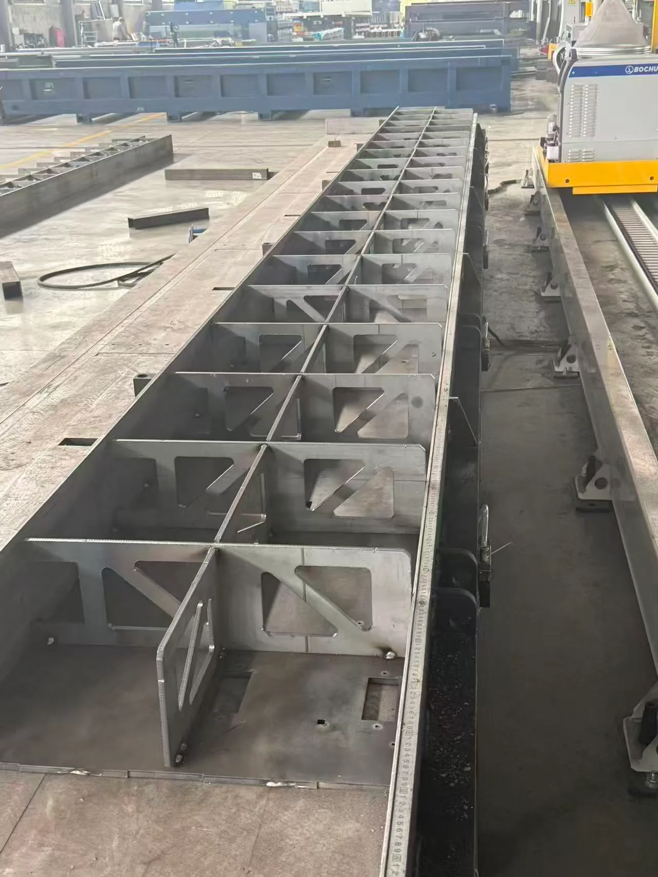
Long steel beam assembly with repeated stiffeners beside a BOCHU rail-mounted system.
Long fabricated member · BOCHU workflow reference

Installation & Support

Industrial robot laser welding an automotive door assembly inside a white enclosed workcell
Contained laser process area · reference · Precitec

Plan the robot foundation or support, part-handling access, utility routes, extraction and maintenance clearance before delivery. Laser cells require suitable beam containment; MIG/MAG cells need controls for arc radiation, fumes and spatter. Positioners and robot movement require appropriate guarding and access controls in either case.

Training should cover tool calibration, frame references, safe teaching, first-part checks, consumable replacement and restart after interruption. Confirm who maintains the fixture, process equipment and robot, since these responsibilities span the whole cell.

Technical Resources

The cell documentation should connect the robot envelope and tool loading with the actual fixture arrangement. Keep the part program, coordinate references and welding process settings together; these records explain how to restore the cell after a fixture move, tool service or controlled product change.

CHENDA’s quality-control approach covers configuration and sample evidence, and the production and delivery process explains the handover information that supports installation. A three-dimensional assembly model with marked seams is the most useful starting point for discussing access.

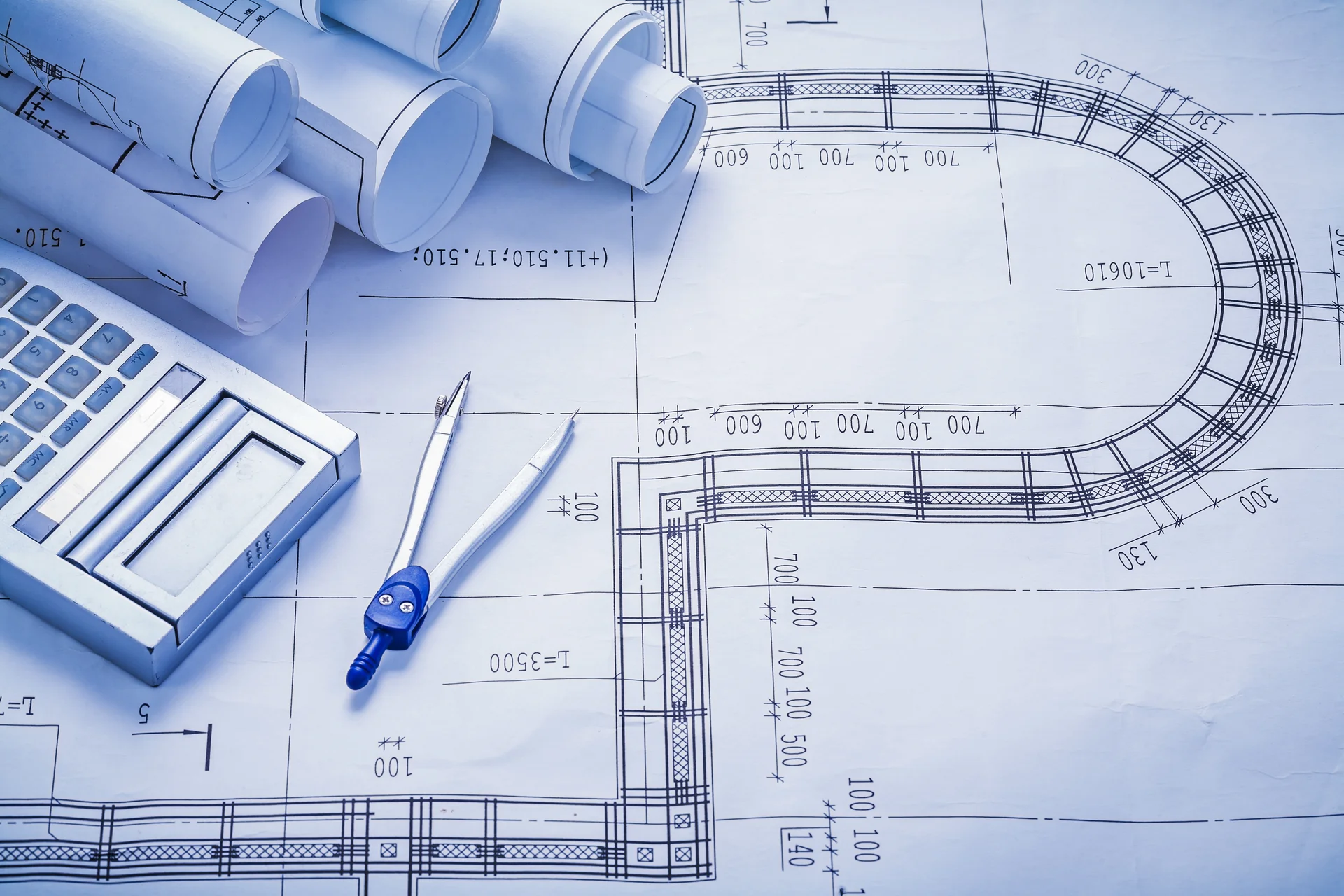
Technical drawings with a calculator and drafting compass
Cell layout and assembly review

Product FAQs

Robot base secured by a triangular bracket with three lever-operated magnetic mounts.
Mounting and cell integration
Steel assembly with triangular stiffeners and visible weld joints.
Visual reference · to be replaced

How do I decide between laser and MIG/MAG on a robot?

Start with the required joint section, fit-up, surface result and material. Laser and arc welding use different heat delivery and filler mechanisms. Compare samples made under the intended conditions before comparing cell price or nominal speed.

Operator teaching an IPG LightWELD laser-welding cobot path on a fixture table
Collaborative application reference · IPG Photonics

Does a collaborative robot need guarding?

The complete application determines the protective measures. The arm’s collaborative functions do not remove laser radiation, arc radiation, fumes, hot metal, sharp parts or positioner hazards.

Long steel beam assembly with repeated stiffeners beside a BOCHU rail-mounted system.
Visual reference · to be replaced

Can one robot cover an entire large frame?

Possibly, but reach alone is insufficient. Tool orientation, cable routing and obstructions can restrict usable coverage. Repositioning, a positioner or additional motion may be needed and must be included in the layout.

JOCRT collaborative robot arm fitted with an arc welding torch.
Visual reference · to be replaced

Do I need seam tracking?

Only when a defined source of variation justifies a compatible sensing system. Reliable part preparation and locating remain valuable. Tracking capability must be demonstrated with the actual material, joint and access conditions.

Steel assembly with triangular stiffeners and visible weld joints.
Visual reference · to be replaced

Can a robot replace welding procedure development?

No. It repeats a programmed motion and process sequence. Appropriate parameters, consumables and inspection criteria still need to be established for the assembly.

Request a Quote

Send the assembly drawing, material, joint details, component variation and required cycle. Include part and fixture weight, access constraints and available floor space. Describe whether the cell will make one product family or change frequently between different assemblies.

Technical drawings with a calculator and drafting compass
Define the assembly and working envelope