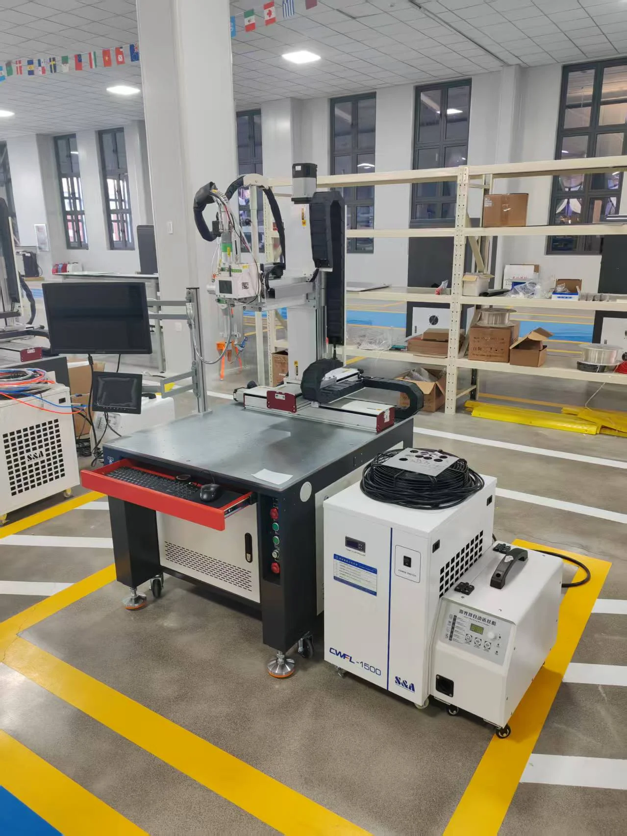
Automatic platform laser welding combines a programmed path with a repeatable fixture. It is designed around parts that can be located consistently and presented to the welding head within a defined working envelope: straight seams, repeated contours, corners and circular joints where suitable rotary motion is provided.
CHENDA automatic laser welding configurations address recurring seams where hand-guided travel is no longer the most useful source of flexibility. A fixed path can join a family of enclosure corners, follow an accessible contour or work around a suitably held circular component. The platform’s value comes from repeating the beam’s relationship to the joint, while a practical fixture keeps loading and changeover manageable.
Steel, stainless steel and selected aluminum-alloy parts can be evaluated according to their joint geometry and surface condition. The machine’s travel range determines where the head can move; the fixture and head-clearance envelope determine which parts can actually be welded.
Can the head complete the seam without a clamp collision?
Planar contour
Coordinated axes and a suitable path
How should energy change through corners and short segments?
Circular joint
Compatible rotary axis and workholding
Is rotation concentric enough for the required joint location?
Several small parts per fixture
Repeatable individual nests
Are all locations accessible and equally well supported?
Complex seams on multiple faces may be better suited to robotic laser welding. Adding axes is useful only when they resolve a real access or orientation requirement.
Features & Engineering
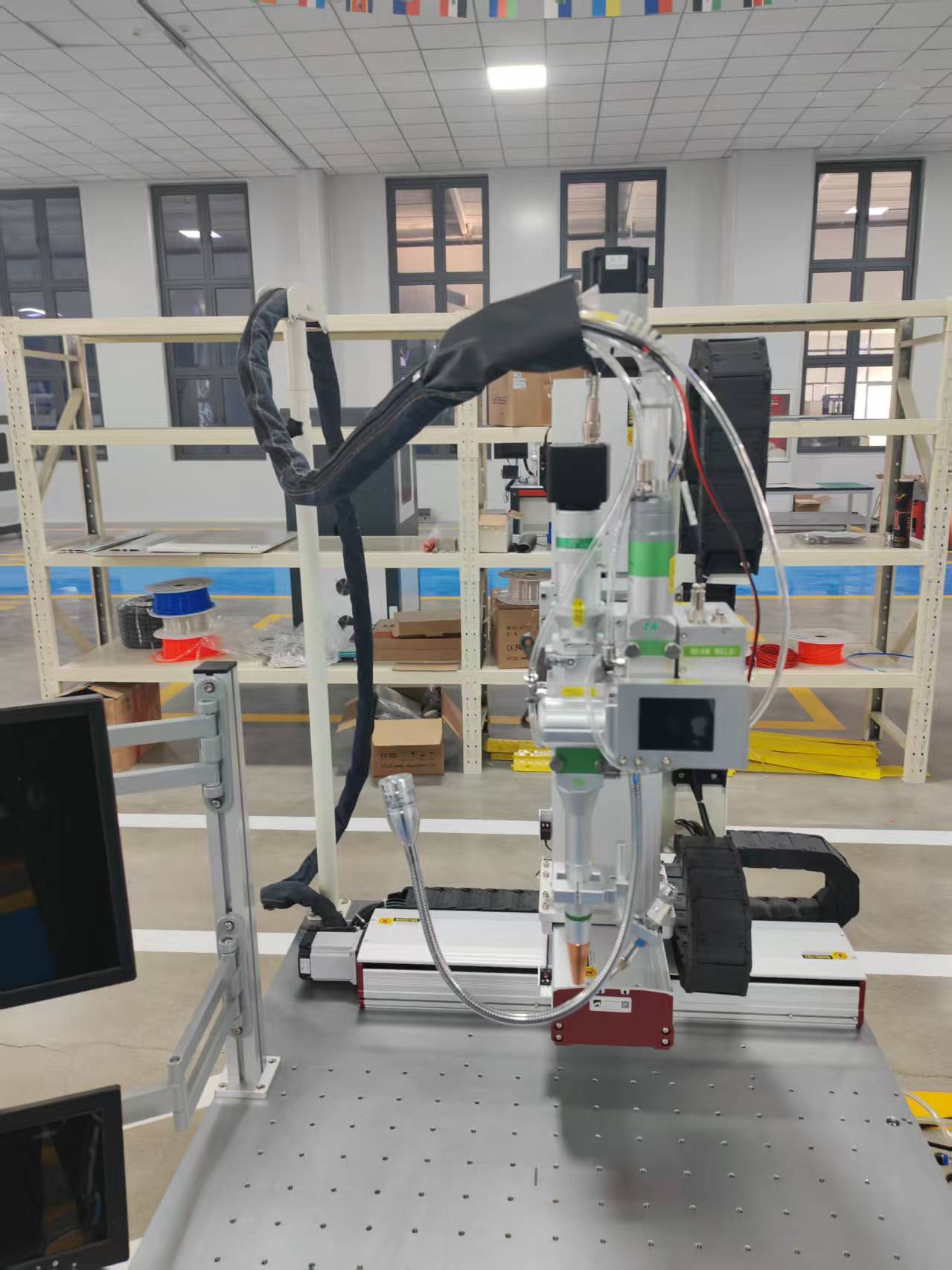
Fixed welding head and axis arrangement
Reference the weld to a stable datum
A fixture must locate the seam, support the part and leave the head’s approach clear. A support plane establishes how the part sits; side and end references determine where the seam returns. Clamps then retain that location. Using a clamp to force a variable part against several conflicting stops can store stress in the assembly or move the seam when the clamp is released.
For a thin formed cover, support close enough to the joint to resist movement while leaving the beam and nozzle path open. Replaceable locating details help separate fixture wear from program adjustment. If an operator repeatedly nudges the path to accommodate a worn stop, the stored program may no longer represent the original geometry.
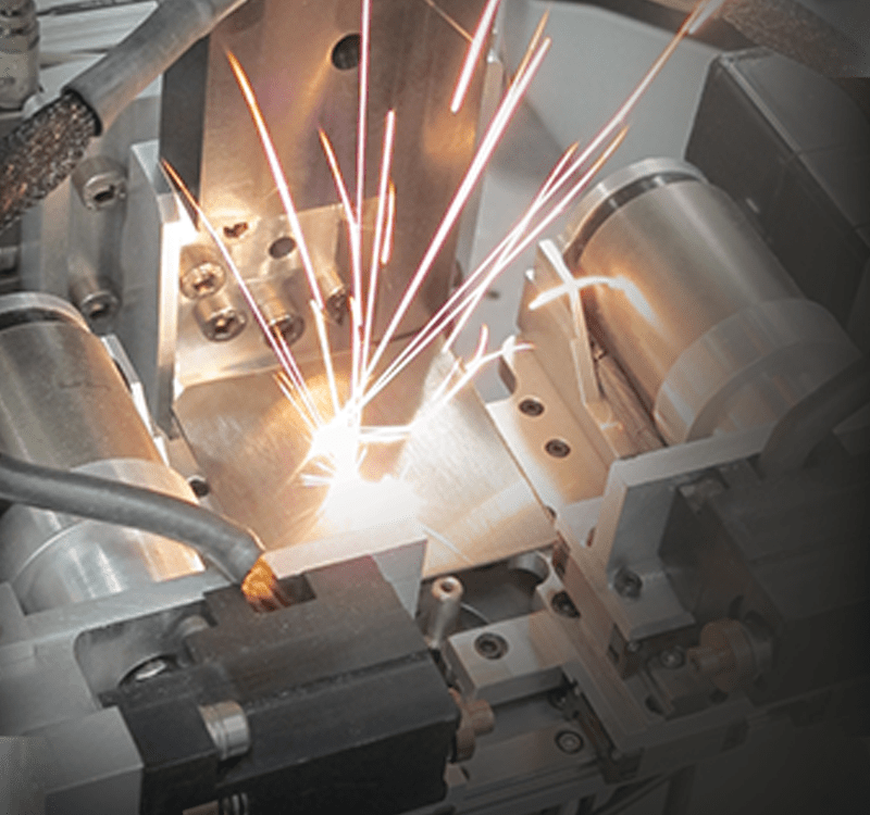
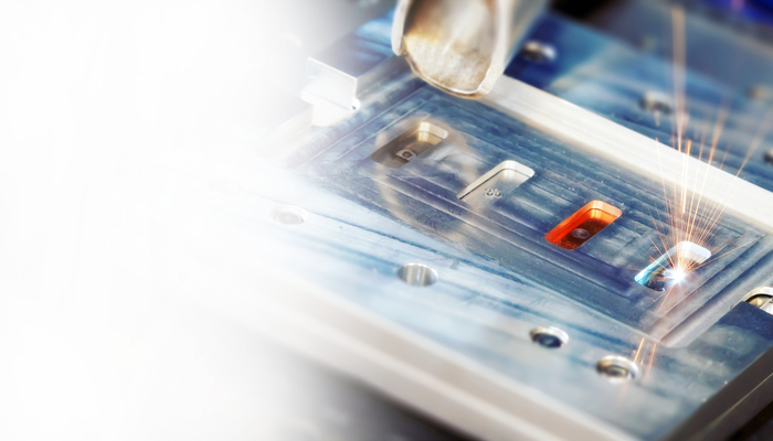
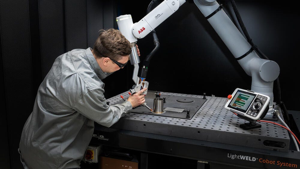
Local laser welding process within a held joint · AMADA WELD TECH
Coordinate speed with laser output
Programmed motion removes hand-travel variation, but corners, short moves and seam ends still need attention. A path that slows down while maintaining the same energy setting can concentrate heat. Motion smoothing can avoid a complete stop, but may change the path near a sharp corner. The selected controller and process must therefore balance contour fidelity, speed and energy rather than assume one constant setting suits every segment.
Seam initiation and termination deserve their own treatment. Gas timing, source response, motion and any filler delivery must begin and end in a coordinated sequence. This is particularly important on short seams, where transitions occupy a larger share of the finished weld.
Separate working travel from usable clearance
Axis stroke, fixture height, focal working distance and nozzle clearance describe different limits. Include the tallest clamp and the loading motion when evaluating the platform. A part can fit on the table yet remain impossible to weld in the intended orientation.
Preserve the working head and table relationship
Preserve the approved setup
Connect each program with its fixture, material and process revision. Controlled setup records help an operator return to the intended focal position, gas setting and wire alignment after a changeover.
Make the control sequence protect the part
In an integrated platform, the cycle should distinguish a command from the condition it is intended to create. A clamp-close command is different from confirmation of the required fixture state; a laser-start command is different from the source being ready. The exact signals depend on the supplied equipment, but the sequence needs defined behavior when a required state is missing.
An interruption also needs a part decision. Restarting from the beginning may overheat an already welded section, while continuing from an arbitrary coordinate may leave a discontinuity. The recovery method should identify the stopped seam and allow the assembly to be assessed before production resumes.
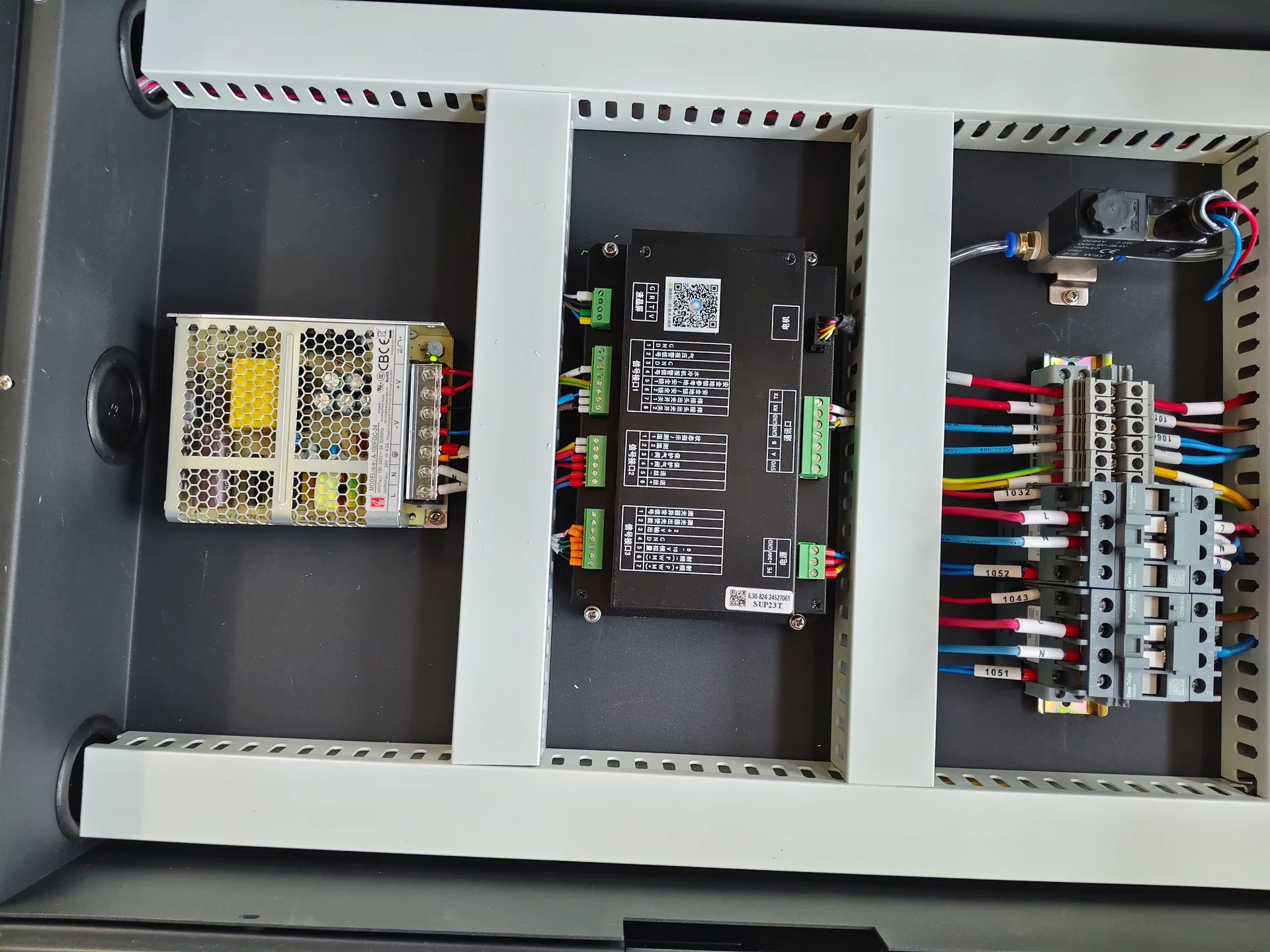
Welding-system control wiring reference
Technical Specifications
An automatic welding configuration is defined by its working envelope and process requirements. Request values for the proposed machine using the following basis.
Parameter
Unit or format
Required context
Linear-axis travel
X/Y/Z travel, mm
Usable stroke with the selected head and fixture
Table size and load
mm; kg
Supported part and fixture weight, including load distribution
Rotary capability
Axis type; diameter, mm; load, kg
Chuck/fixture arrangement and coordinated-motion requirement
Laser output
W
Material, joint and target penetration
Positioning characteristics
mm under stated measurement conditions
Axis performance; separate from finished weld quality
Programmed travel
mm/s or mm/min
Welding feed versus non-processing movement
Filler wire
Alloy; diameter, mm; feed, m/min
Required bead geometry and feeder compatibility
Complete cycle
s per accepted assembly
Load, clamp, weld, release and unload time
Electrical and cooling services
V, phase, Hz, kW; cooling requirements
Complete configured system
Table dimensions are not equivalent to welding travel, and axis repeatability is not a guarantee of seam position on a variable part. The fixture, component tolerance and thermal movement contribute to the final result.
A larger X/Y stroke helps cover a larger path, but does not create extra clearance beneath a low-mounted head. Additional Z movement may serve setup height rather than coordinated welding on a spatial contour. A rotary device may index the component between stationary seams or rotate continuously while welding. These functions are different; the usable part range follows the actual motion and control arrangement.
Use more than one production part during a trial. Repeat loading and unloading to check whether the fixture consistently places the seam beneath the programmed path. Include the normal variation from cutting, bending or machining.
For a contour, inspect corner transitions and seam termination as well as the straight sections. For a circular joint, assess runout and the overlap region. Review finished dimensions after cooling and fixture release, then apply the agreed weld inspection method.
If a defect recurs at the same program position on every part, examine the local path, speed transition, access and process timing. If its position changes between parts, incoming geometry or locating variation may be more relevant. This distinction helps direct improvement toward the motion program or the physical setup rather than changing both without a clear reason.
Discuss the axis layout, laser source, processing head, controller, cooling, enclosure and fixture as one operating system. A rotary axis, wire feeder, viewing camera or additional fixture station may suit particular parts. Each needs mechanical clearance and control compatibility.
Part detection, clamp confirmation and process monitoring can be considered for repetitive production. These functions should have a defined purpose, such as preventing a cycle on a missing component or detecting a specific process fault. A camera used for operator viewing is not automatically a seam-tracking or weld-inspection system.
For multiple nests on one table, the configuration must also manage identity: which nests are loaded, which program applies and which locations have completed a cycle. More fixture positions can reduce handling per part, but only if the head can reach them without long non-processing moves or different thermal conditions that alter the result.
Platform welding is a practical direction for recurring enclosure components, brackets, small metal assemblies and accessible seams with consistent geometry. A typical workflow is prepare and inspect parts, load to the fixture datums, clamp, run the welding program, allow the required cooling and release the assembly.
Arrange upstream work so the welding station receives compatible batches and identifiable material. If loading takes longer than welding, review fixture handling before specifying a faster motion system. If several variants share the same family, consider how locating inserts and programs will change without confusing operators.
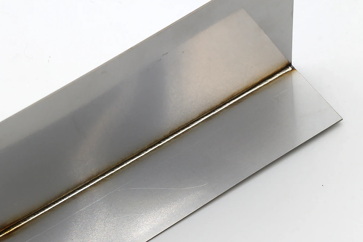
Consider a recurring folded enclosure with accessible outer seams. The fixture can reference a stable face and locating features, leaving the corners free. The program follows the required sequence, while the operator inspects the returned part for fit and surface condition. A circular collar presents a different task: concentric location and controlled rotation matter more than a broad rectangular table. Both are platform applications, but their useful options and setup risks are different.
Prepare a stable installation area with suitable electrical supply, extraction, cooling ventilation and loading access. The laser enclosure and access controls must suit the operating modes and workpiece openings. Confirm how service access and maintenance differ from normal production access.
Training should cover fixture setup, program selection, dry runs, focal-position checks, first-part approval and recovery after an interrupted cycle. Back up approved programs and retain the corresponding fixture/setup records.
The technical package should distinguish the machine layout from the fixture layout. The first describes travels, services and access; the second shows part datums, clamping and the exposed seam. Together with the approved program and material record, they explain how the machine produces the intended joint.
CHENDA’s quality-control process connects configuration checks with sample evidence, while production and delivery information helps prepare the installation and handover. Include the part CAD format and program-transfer needs when discussing controller compatibility.
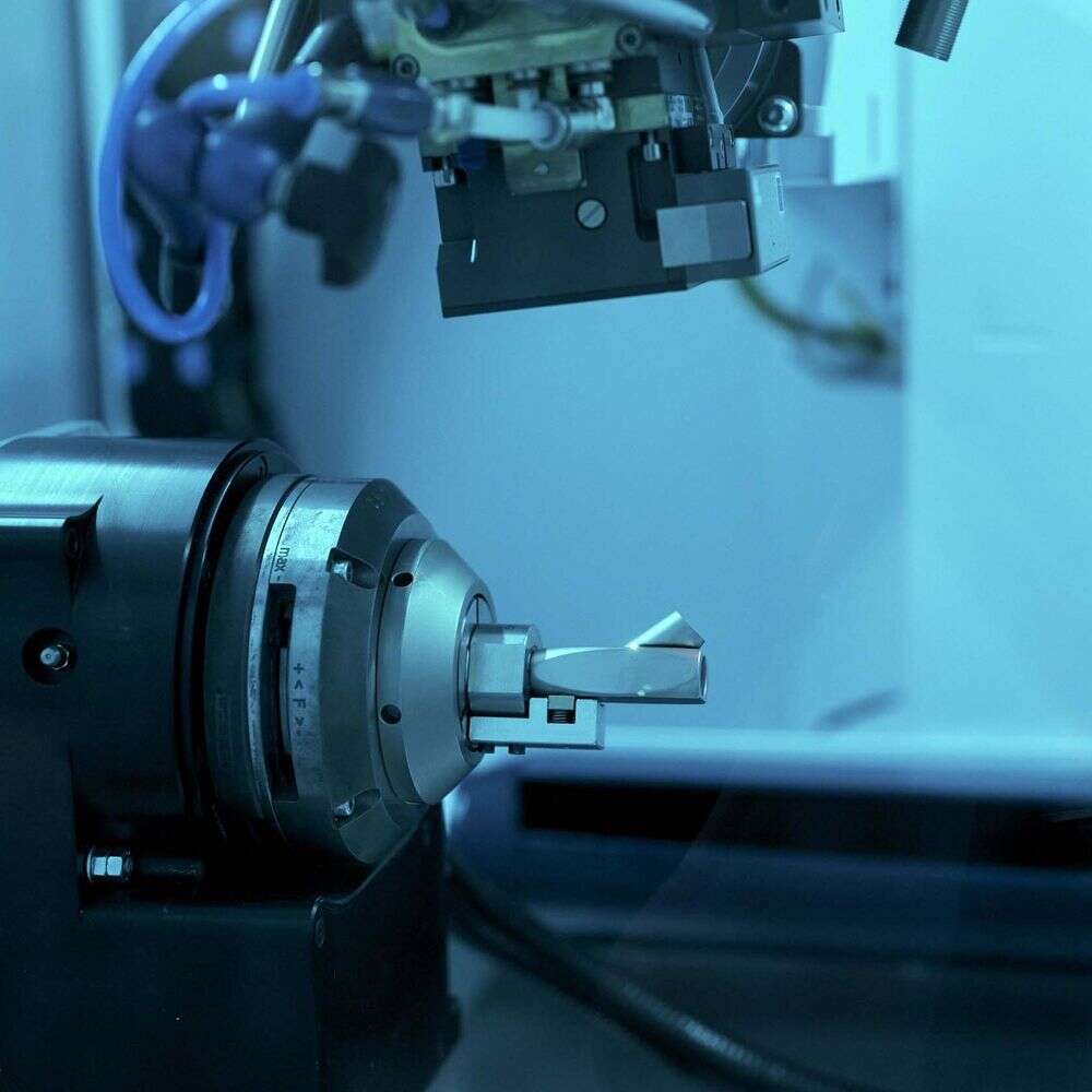
Machine layout and fixture layout · review reference
Product FAQs
Head and table arrangement
Does automatic welding include automatic loading?
Not necessarily. A platform may automate the welding path while an operator loads and clamps each assembly. Loading equipment and additional stations are separate configuration decisions.
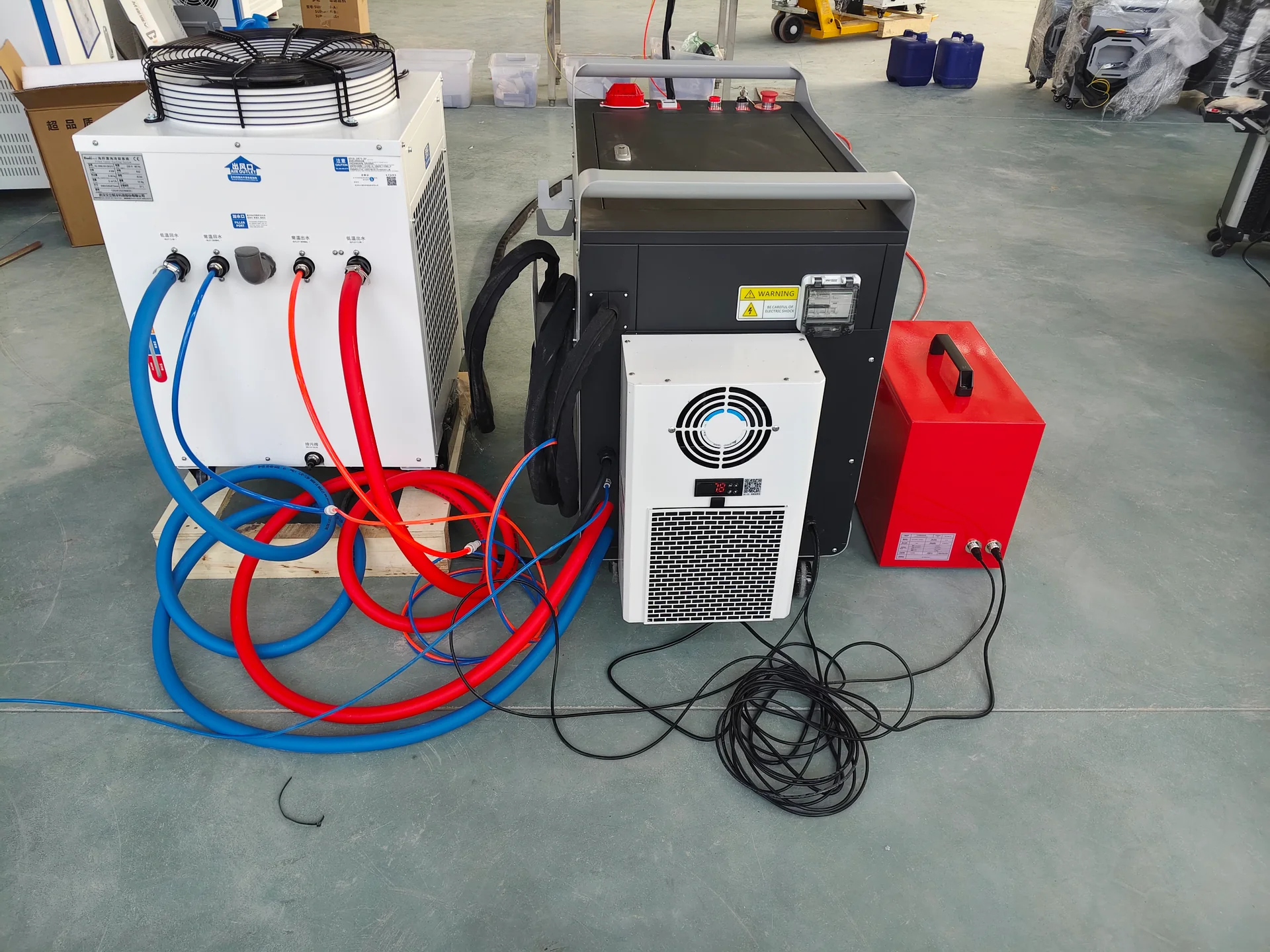
Visual reference · to be replaced
Can a drawing be sent directly to the machine for welding?
The drawing must be translated into a weld path tied to the actual fixture and part datum. Compatible file formats, programming methods and any path-editing requirements depend on the selected controller.
Is a platform better than a robot for a straight seam?
A platform can offer a direct motion arrangement for accessible, repeated seams. A robot becomes useful when orientation or access changes substantially. Compare the entire fixture and handling task, not only the seam shape.
Sometimes. Adjustable or interchangeable locating elements can support a product family, but each setting must preserve joint position, clamp access and program identity. Excessive adjustment can undermine the consistency automation is intended to provide.
Not by itself. Stable fit-up remains essential. Any sensing or adaptive capability must be explicitly configured and tested against the expected variation.
Send the part drawing, material, thickness, seam locations and fixture concept if available. Include the largest assembly, normal part variation, batch mix and target cycle. Mark which faces must remain accessible and which surfaces must be protected from clamping marks.