Tube fabrication / Fiber laser

Tube Laser Cutting Machines

Product Overview

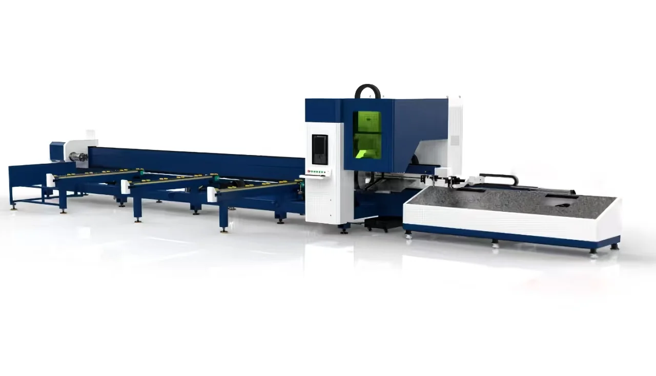
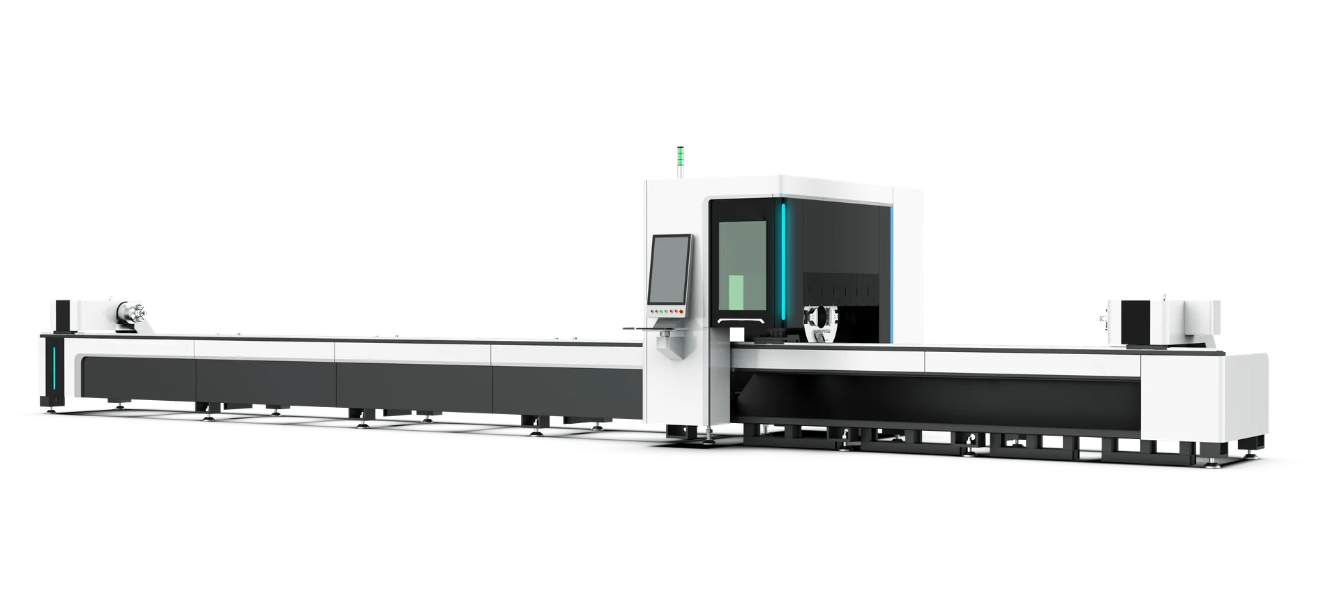
Cut tube length, openings and assembly features in a coordinated process. CHENDA’s tube laser range covers general tube fabrication, larger sections and configurations that address loading, support and finished-part removal. It is suited to evaluating repeatable frame components as well as varied tube jobs that would otherwise move between separate cutting and hole-making operations.

The central selection question is how the machine controls your tube throughout the cut. Chuck range, support position, stock straightness, rotating clearance and finished-part length must work together. Laser power is one part of that system.

Tube laser cutting machine with a central cutting enclosure and long chuck-support beds

Materials & Capabilities

Carbon steel and stainless steel tubes are common starting materials. Aluminum alloy and other compatible metal tubes require a process review for the selected equipment. Round, square and rectangular stock must be assessed using its actual dimensions, wall thickness, mass and shape.

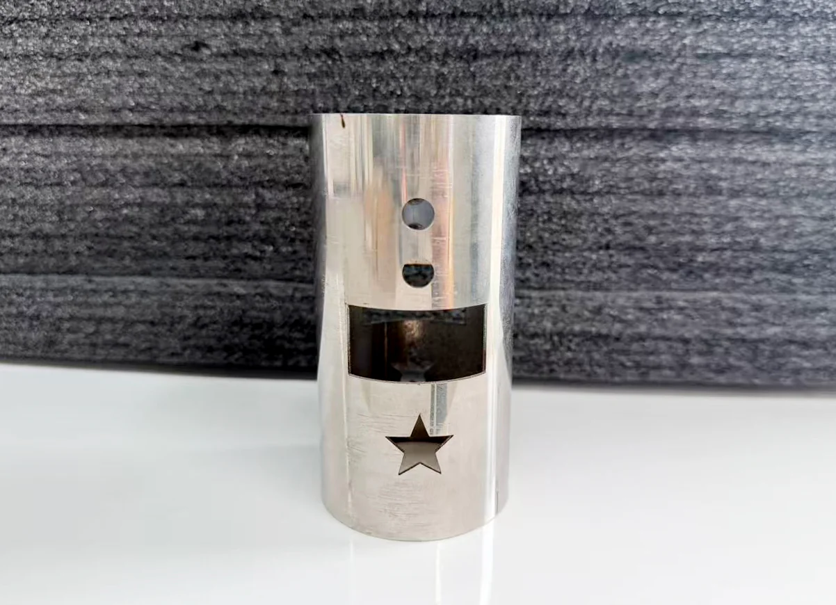
Tube laser cutting can be evaluated for end contours, slots, through-holes and intersecting features used in frames and assemblies. An accurately defined mating profile can help position two members before welding. The required joint gap and finished weld still depend on the drawing, incoming tube and downstream process.

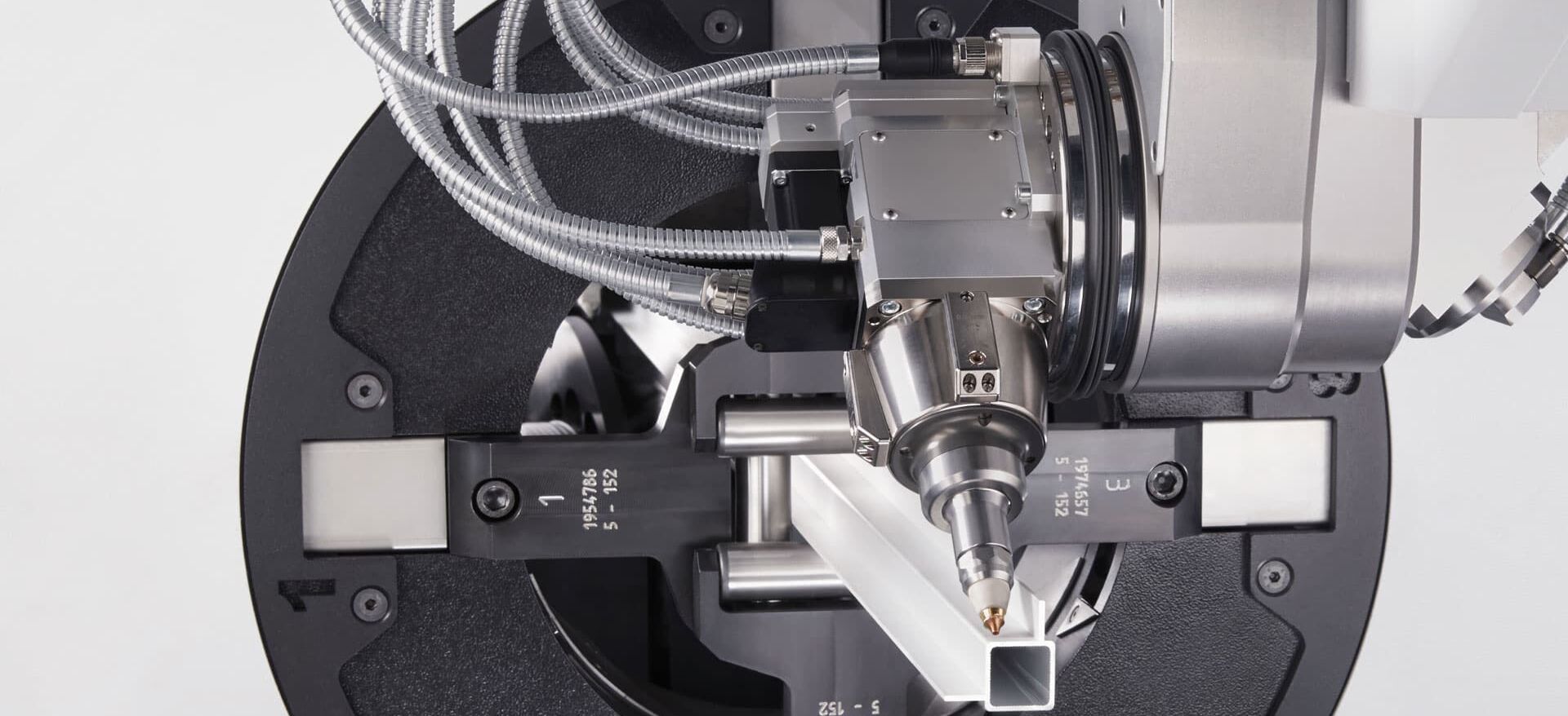
Do not describe a rectangular tube by one side alone. Its diagonal affects the space needed during rotation, while jaw contact and support geometry determine whether it can be held reliably. Bow, twist and the weld-seam position also matter when a feature must remain aligned to a particular face.

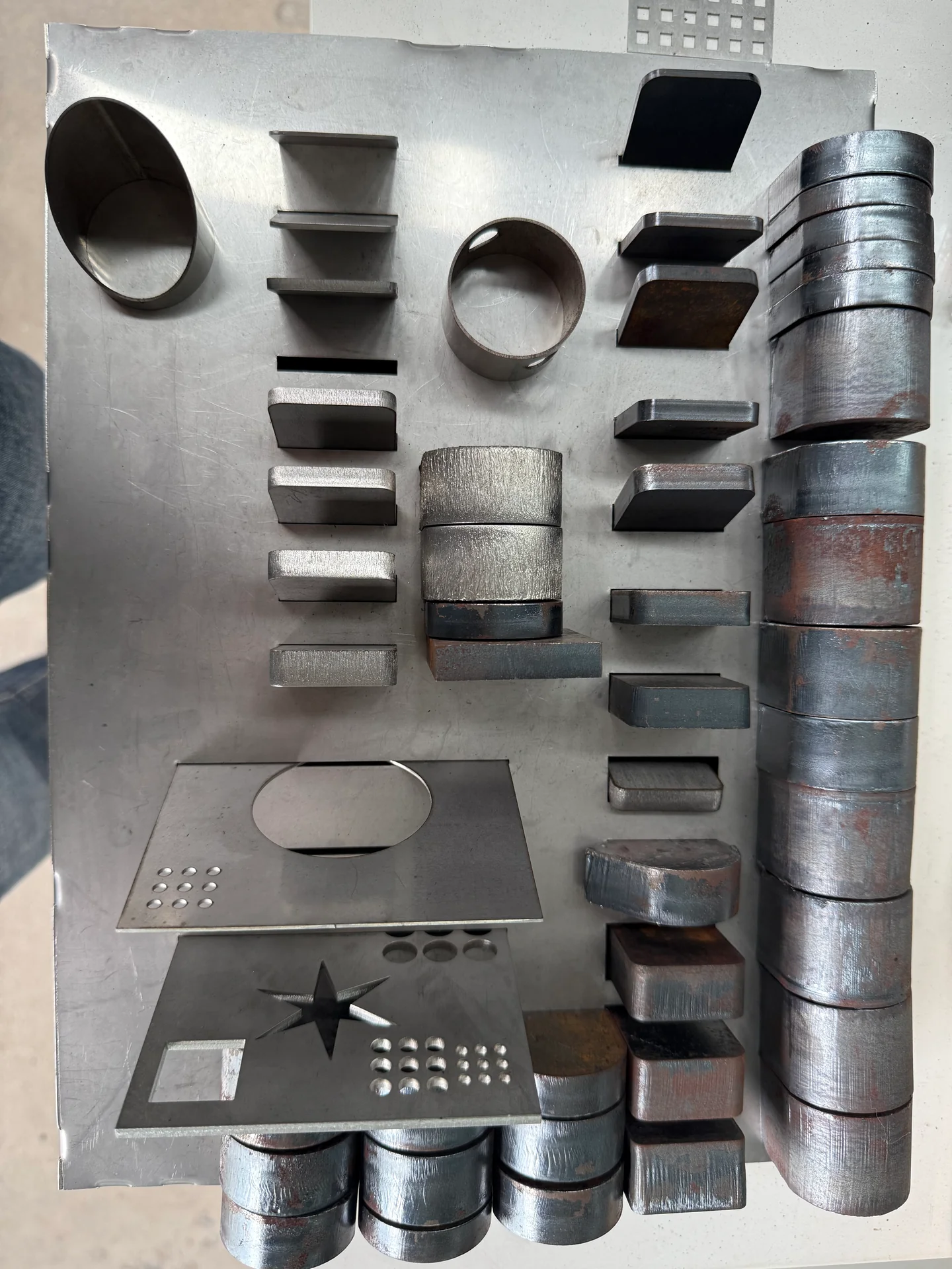
Round metal tube sample with circular holes, a rectangular window and a star-shaped opening
Cut tube geometry reference
Third-party photograph of a square tube held inside a rotary chuck with the laser head near its open end
Section contact and chuck clearance · Franke GmbH / TRUMPF customer story; individual photographer not stated

Does a 100 × 50 mm rectangular tube fit a 120 mm range?

An ideal 100 × 50 mm rectangle has a diagonal of approximately 111.8 mm, ignoring corner radii. That calculation describes a rotational envelope, not an approval to cut it on a particular chuck. Jaw travel, contact position, support shape and the permitted section range still govern fit. A catalog round-tube diameter and a rectangular-tube size should therefore remain separate specification fields.

Welded tube introduces another consideration: the longitudinal seam may need to stay away from a functional opening or a visible joint. When orientation matters, the process needs a reliable way to identify and preserve that reference from loading to cutting. Automatic seam detection is a specific function to include where required, not an inherent feature of every tube laser.
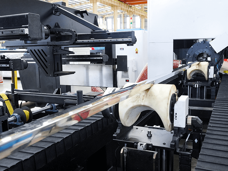
Third-party photograph of a long round tube resting on shaped auxiliary support rollers along a laser machine bed
Supporting the free length of the tube · ADH Machine Tool

Chuck control and tube support

The catalog tube families use pneumatic clamping and dedicated supports. Centering establishes a reference; support reduces movement in the stock extending beyond the chuck. Thin-wall tubing needs enough grip to transmit rotation without crushing or marking the section. Simply increasing clamping pressure may exchange slipping for deformation.

During cutting, the supported length changes. A long stock item may begin with several supports beneath it and finish as a short remnant with a long finished part on the opposite side of the head. The support sequence must follow that change. This is why finished-part length belongs beside maximum stock length in a capacity discussion.

Three-chuck and heavy-duty arrangements

The catalog TP direction describes movable three-chuck handling with independently controlled supports at the feeding and cutting ends. The TX direction adds a side-mounted layout for heavier stock. Their purpose is to control the member as it moves through the cutting area and as the final pieces are released.

An additional chuck can grip or support stock where another chuck would otherwise need clearance from the cutting head. The useful result depends on the transfer sequence and available travel. Residual length should be evaluated on the actual nest: a favorable final part can use stock that a different part sequence cannot reach. A short-tail arrangement is not the same as a promise of zero waste across all shapes.

Third-party photograph of a square tube held inside a rotary chuck with the laser head near its open end
Chuck and cutting-head relationship · configuration reference · Franke GmbH / TRUMPF customer story; individual photographer not stated
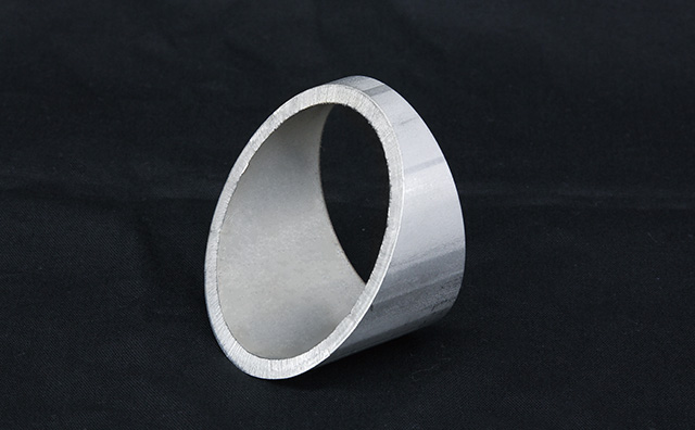
Third-party photograph of an angled-cut metal tube ring with its cut edge visible against a dark background
The inner and outer edge of a tube cut · Mazak Optonics

Control the inside as well as the outside

The beam must cut the intended wall without unacceptable damage or spatter on the opposite internal surface. Tube diameter, wall thickness, feature position and process setup affect the result. Internal cleanliness may need a separate requirement when the component carries fluid or has an exposed interior.

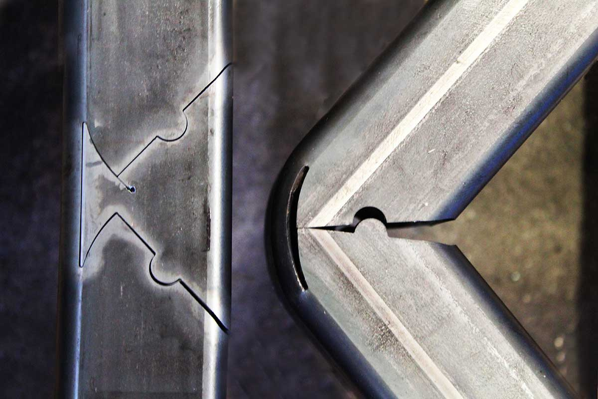
Third-party square-tube sample showing laser-cut relief geometry before and after forming a corner
Folded and interlocking tube features · Tecnocurve

Why a tube corner needs a different process from a flat face

As a rectangular tube rotates, the head crosses flat faces and rounded corners. The surface direction and nozzle relationship change through that transition. A satisfactory long cut on one flat face does not establish a clean small hole near a corner. Coordinated motion, height following and suitable local cutting conditions help maintain the intended edge without excessive heat at the transition.

The design of an assembly opening also matters. A hole that looks correct on the outside can leave an inner-wall edge that interferes with the inserted member. Wall thickness and the angle at which the mating tube enters determine the required clearance. A physical fit-up test reveals this more clearly than checking only the outside outline.

Technical Specifications

These model references and ranges are listed in the CHENDA catalog. They describe catalog configurations; confirm the selected chuck, loading system and current offered specification for your tube geometry.

Tube laser cutting machine with a central cutting enclosure and long chuck-support beds
Catalog model Listed round-tube clamping range, mm Listed tube length, m Catalog laser-power range, kW
CHD-T120 Ø16-120 6.5 1.5-4
CHD-T160 Ø10-160 6.5 1.5-4
CHD-T220 Ø10-220 6.5 1.5-4
CHD-T240 Ø20-240 6.5 / 9.2 1.5-4
CHD-T360 Ø20-360 6.5 / 9.2 1.5-4

The two lengths shown for the larger models are catalog length variants, not a statement that every supplied machine includes both. A round-tube clamping range does not establish square- or rectangular-tube capacity. Review those dimensions separately.

Other required field Unit Application condition
Tube wall thickness mm Material grade, joint geometry and desired edge
Stock mass kg per tube and kg/m Chuck load, support spacing and handling
Finished-part length mm Collection support and risk of movement at separation
Residual stock length mm per nest Chuck clearance, end trim and final part arrangement
Bevel requirement Degrees; root face in mm Cutting-head access and downstream weld detail
Production demand Accepted parts/hour Includes feeding, rotation, cutting and collection

Material yield includes more than the chuck tail

Usable yield depends on end trimming, cut width, spacing between parts, rejected stock regions and the final remnant. Common-line or interlocking nesting may reduce unused length for suitable geometries, but it changes the cutting sequence and separation behavior. A nesting report should therefore be assessed together with the collection method. Saving a short length of tube has little value if the newly nested part becomes difficult to release without damage.

For frame production, compare yield using a full set of required members rather than repeating whichever individual part nests most efficiently. The complete frame needs its long and short pieces in the right quantities.

Third-party photograph of an angled-cut metal tube ring with its cut edge visible against a dark background
Cut section and edge reference · Mazak Optonics

Samples & Demonstration

Third-party square-tube sample showing laser-cut relief geometry before and after forming a corner
Tube feature and corner reference · Tecnocurve

A useful test contains a complete frame connection. Cut the two mating tube pieces, check hole orientation and assemble them before judging the result. Include the smallest relevant section, a thin-wall component and a long part when these occur in normal production.

During the demonstration, observe support movement, tube rotation and the way the finished piece separates. Inspect internal spatter, end squareness, hole location and the joint gap. Record the remaining tail from the selected stock length so material yield can be compared on a common basis.

A useful acceptance sequence includes a part from the beginning of the stock and another near its end. This challenges both normal support and the final clamping condition. Use the same datum for measurements on opposite faces; otherwise, two individually correct holes may still be incorrectly oriented to one another. Record the seam position if it affects the joint. These checks give the quality-control record a direct connection to assembled-frame consistency.

Configuration & Options

Tube laser cutter with a side loading rack, enclosed cutting area and collection tray
Loading-line configuration reference

Discuss the required chuck arrangement, jaws, intermediate supports and finished-part support first. The proposed configuration should then identify the source, head, control, tube-nesting software, cooling and gas system.

Automatic feeding is most useful when the stock shape and length are compatible with the loader. A bundle-feeding system has to separate one tube, orient it where necessary and place it into the feed path. Mixed sections or damaged stock ends can interrupt that sequence even when each tube is individually within the cutting range.

At the output, a collection tray suitable for short pieces may not support a long, thin finished member. Surface-sensitive furniture tubes can also need contact arrangements that avoid marking. Bundle loading, individual loading, supported unloading and bevel functions are therefore separate choices with their own working ranges.

Where the programming package supports micro-joints, a small retained connection can hold an otherwise loose piece until removal. The tradeoff is an additional separation point to finish. Software options should be chosen for the actual part behavior, with their license and machine integration identified in the supplied configuration.

Applications & Workflow

Tube lasers can support metal furniture, exercise-equipment frames, machine frames and fabricated tubular assemblies. In metal furniture production, a well-defined slot or locating feature can simplify fixture loading and keep similar members correctly oriented.

The route is stock identification, loading, locating, cutting, part collection, edge preparation and assembly. In a repeated frame, accurately placed slots can locate crossmembers and reduce manual measuring in the fixture. They still need clearance appropriate to the incoming tube and welding method: an unnecessarily tight joint can make assembly slower, while an oversized opening can defeat the locating benefit.

Keep the program revision with the part batch. For long or visually similar components, identification at collection helps prevent incorrect parts entering a welding fixture. Preparing the full set together is particularly useful when left- and right-hand members differ only in the orientation of one opening.

When structural sections exceed the geometry or load appropriate for a tube machine, review profile laser cutting as a separate equipment route.

Third-party square-tube sample showing laser-cut relief geometry before and after forming a corner
Cut features designed for assembly · Tecnocurve

Installation & Support

Third-party photograph of a long round tube resting on shaped auxiliary support rollers along a laser machine bed
Plan the stock path · ADH Machine Tool

Plan space along the complete stock path and on the discharge side. Provide a safe way to load a bundle or individual tube without crossing the operator’s normal working area. Supports, chuck access and scrap collection need clearance for setup and cleaning.

Training should address section setup, jaw inspection, support adjustment, program orientation, remnant handling and recovery after an interrupted cut. Use installation and training support to define the handover scope and request support for machine-specific operating questions.

Handover should also preserve the working relationship between jaws, supports and the demonstrated section. Recording those settings alongside the successful part program gives a new operator a practical setup reference. The production and delivery page explains how machine and accessory identification stays connected through shipment.

Technical drawings with a calculator and drafting compass
Layout and drawing review · reference

Technical Resources

Request the chuck and section-capacity table, loading diagram, finished-part collection limits and proposed tube-nesting functions. A demonstration plan should identify material grade, shape, wall thickness and both stock and finished lengths.

Product FAQs

Assorted metal plate and tube samples displaying cut edges and openings
Round metal tube sample with circular holes, a rectangular window and a star-shaped opening

Can a maximum-diameter tube rating be used for square tube?

No. Square and rectangular sections have different rotating envelopes and jaw-contact conditions. Provide both outside dimensions and the wall thickness so clearance and clamping can be checked together.

Third-party photograph of a long round tube resting on shaped auxiliary support rollers along a laser machine bed
Stock support reference · ADH Machine Tool

Can the machine correct badly bent tube?

Locating and compensation functions, where supplied, have operating limits. They do not make every bowed or twisted tube suitable. Incoming-material tolerances should be agreed with the process requirement.

Tube laser cutter with a side loading rack, enclosed cutting area and collection tray

What determines whether automatic loading is worthwhile?

Consider batch size, section changes, bundle consistency, loading labor and the unloading method. A loader should be evaluated across the actual product mix, including changeover, rather than on one repeat part alone.

Third-party square-tube sample showing laser-cut relief geometry before and after forming a corner
Joint geometry reference · Tecnocurve

Will the laser-cut connection be ready for welding?

Check fit-up, edge condition and internal contamination against the welding method. Some joints benefit from locating features; others require deburring, cleaning or a specified bevel before welding.

Request a Quote

Send section drawings, material grades, wall thicknesses, stock lengths and finished-part lengths. Include tube mass, critical orientation features, joint details and expected batches. Photographs of the incoming tube and loading area help explain handling constraints that a part drawing may not show.

Round metal tube sample with circular holes, a rectangular window and a star-shaped opening