Profile Laser Cutting Machines for Structural Steel
Product Overview
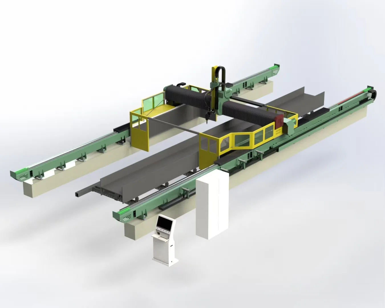
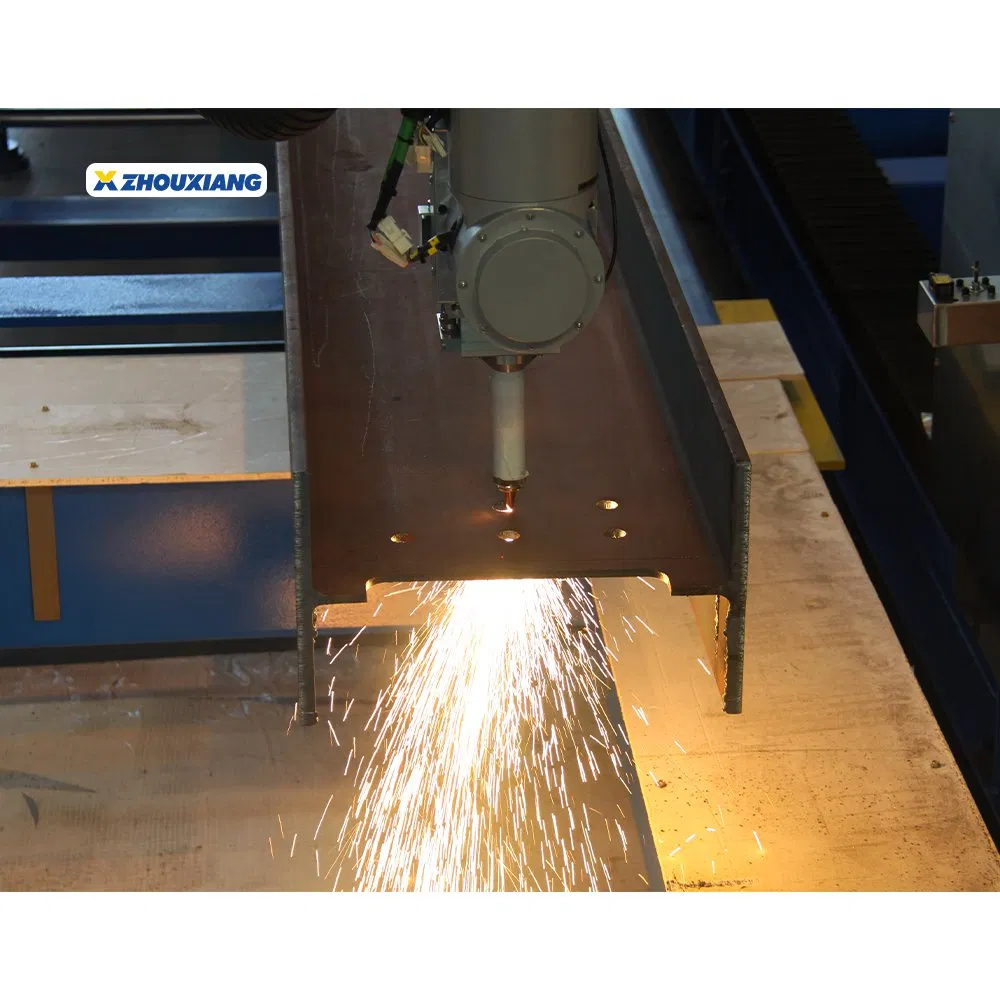
Prepare structural members with cutting, holes and connection details in a coordinated process. CHENDA’s profile laser cutting direction addresses H-beams, I-beams and channels whose web, flanges and weight require a different machine arrangement from ordinary sheet or small-tube cutting.
The HR series presented in the CHENDA catalog combines profile cutting with hole and groove processing. Its value is the possibility of reducing repeated positioning as a member moves from stock to a prepared fabrication component. Selection starts with the section geometry and connection drawing, including where the head must reach and how the member is supported.
The principal application is structural steel in H, I and channel sections. A profile description should include the section designation, actual height and width, web thickness, flange thickness, root radii and material grade. Rolled and fabricated members may have different dimensional variation and surface conditions.
Potential operations include cutting to length, openings in accessible faces, connection notches and suitable bevel preparation. The required access depends on the head arrangement and the relationship between web and flange. Features close to a root radius or behind a flange need specific review.
A structural member’s external size is only part of its processing envelope. Flange thickness, bevel angle, head clearance and support location can restrict a feature even when the complete section fits within the machine.
Usually a different thickness and orientation from the flange
Hole and contour conditions must follow the actual web
Flange
Access may be limited by the adjacent web or opposite flange
A suitable head path and support arrangement are essential
Web-to-flange root
The radius adds material and changes the local surface
A detail near the root cannot be treated as a cut in uniform flat plate
Prepared member end
Material may become less stable as the final connection separates
Cut order and support affect the outgoing geometry
On a fabricated beam, welds and local buildup can create another change in surface height or thickness. The process model should represent the actual member closely enough to distinguish these regions. A single nominal thickness is not an adequate description for the complete section.
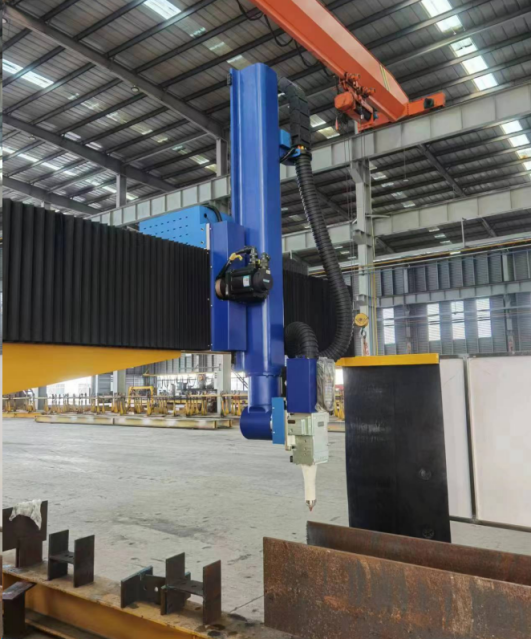
Long, heavy stock needs support during loading, locating, processing and discharge. A stable datum matters when bolt groups or connection features are positioned along the member. Support placement must allow cutting access while preventing movement as material is removed.
Support under a long beam limits sag between contact points. The supports also have to leave the cutting path clear. Removing an end notch or cutting a member into shorter pieces changes the balance of the workpiece, so a setup that is stable before the first cut may not remain so at the last separation. The loading and discharge design is therefore part of cut quality as well as factory logistics.
The HR catalog describes cutting, holes, notches and bevel-related processing in one equipment direction. Combining those operations around a consistent reference can reduce transfers between separate marking, sawing and feature-preparation stations. The resulting value is greatest when the prepared features stay correctly related to one another, so the fabrication team does less repeated measuring during fit-up.
This does not require every feature to be finished by laser. A production route can use the laser for accessible contours and rough preparation while retaining a separate operation for a hole or surface that has a different finished requirement. The connection drawing determines that division.
Account for real section shape
Nominal design dimensions do not fully describe a delivered beam. Bow, twist and local dimensional variation affect where the surface lies relative to the programmed path. Discuss the locating, calibration and compensation functions of the proposed system, together with their operating limits.
Measurement or profiling, where included, can establish the real surface position for the control. It cannot make an out-of-tolerance beam straight or guarantee that all connection geometry fits within the remaining material. The practical benefit is a better relationship between the intended toolpath and the actual workpiece, within the agreed incoming-stock condition.
Relating the head position to the steel section · Fortune Laser
Separate marking equipment reference
Keep member identity connected to assembly
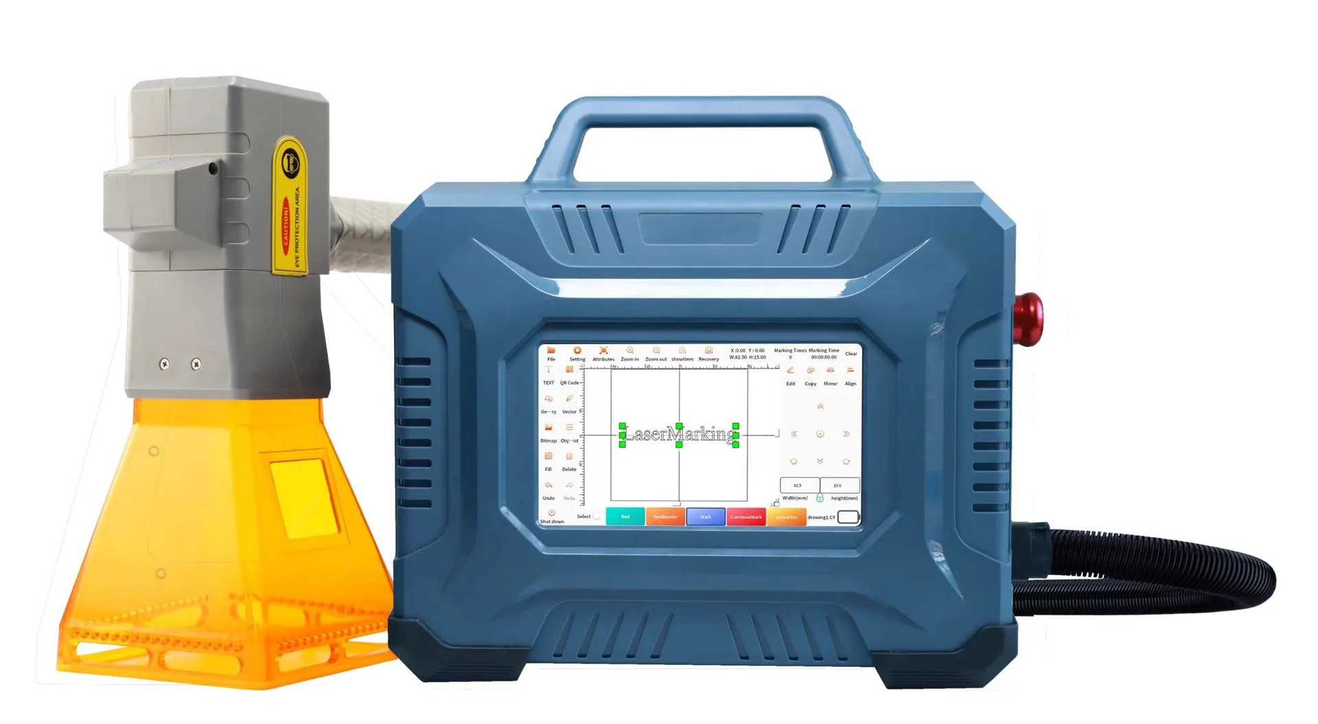
Part identification and welding-location marking are listed as HR process functions. Where included in the supplied configuration, these can help connect a cut member to its fabrication drawing and assembly position. Confirm the marking method, visibility and compatibility with later surface preparation.
Drawing and datum review · reference
Preserve the datum through connection preparation
A bolt group can be internally consistent but still be incorrectly positioned along the member. The program and inspection plan need the same reference end, orientation and face designation. This becomes particularly important with mirrored members or a beam whose two ends have different connection details. Clear member identity and datum definition allow the cut component to reach assembly with an unambiguous orientation.
Technical Specifications
The following figures are listed for the HR profile-cutting reference in the CHENDA catalog. They are preliminary selection references for that catalog arrangement, not capacities to apply to every profile machine or every beam shape.
Catalog HR reference item
Listed value
Condition to resolve for the project
Profile types
H-beam, I-beam, channel steel; plate also listed
Confirm the processing setup for each stock form
Minimum feeding length
2.5 m
Support and feed requirements for short stock
Maximum profile feeding length
12.5 m
Incoming member and handling arrangement
Profile cross-section
1,250 × 650 mm, height × width
Usable envelope for the actual section and head path
Maximum profile weight
10 t
Permissible load for the proposed support and feed system
Listed machine dimensions
34 × 10 × 5.2 m, length × width × height
Confirm current layout, lifting and service clearances
Power and cutting thickness must be specified separately for the proposed laser and material. A beam may have different web and flange thicknesses, and a bevel creates a different cutting condition from a perpendicular cut.
The technical proposal should also state finished-member length, hole and contour tolerances in mm, bevel angles in degrees, root-face dimensions in mm, processing access and the method used to measure acceptance parts. Head-axis travel alone is not proof that every weld-preparation geometry is achievable.
Why bevel capacity differs from straight-cut thickness
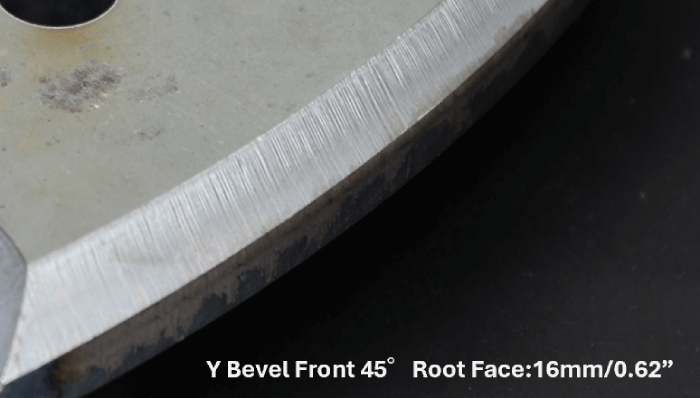
An inclined cut travels farther through the material. In a simplified flat-plate example, a 20 mm thickness cut at 45° from the surface normal creates a material path of about 28.3 mm before allowing for a retained root face or other joint detail. This is a geometry illustration, not a machine capacity rating.
The head also needs room to tilt without the nozzle or body approaching an adjacent flange. Bevel angle, effective material path, root face and local access therefore have to be considered together. A straight-cut thickness figure or a head’s maximum tilt angle alone cannot establish that a particular weld preparation will work.
Bevel and retained root face · original manufacturer sample · TANAKA AmericaComplete member workflow · reference
Useful output is a prepared member, not a single hole
Production time includes lifting, locating, surface measurement where used, cutting across the required faces and discharging the member. For a long beam with only a few features, handling may dominate. A member with many connection details may gain more from combining preparation steps. Compare complete members from the expected project mix, keeping any remaining drilling, grinding or marking in the route.
Choose a representative connection segment with a web feature, a flange feature and the intended end detail. Include the actual steel grade and surface condition. A test should show how the member is located and supported before the head approaches the connection area.
Measure hole positions from the agreed member datum. Inspect end geometry, access near the flange root, residual dross and any specified bevel or root face. Where the part enters a bolted or welded assembly, check that fit-up as part of the demonstration.
For a bolted connection, distinguish hole size, hole shape, relative spacing and position on the member. Each can affect assembly differently. For a weld preparation, inspect more than the visible top edge: the land and angle along the cut must support the intended joint. A flange-side photograph alone does not establish the complete geometry.
The sample record should identify where a feature was measured and from which datum, with enough information to repeat the assessment. This connects the demonstration to CHENDA’s quality-control process without treating an attractive sample as proof of every future connection type.
Define the feed system, support arrangement, cutting-head access and finished-member removal together. The proposed configuration should identify the laser source and power, head, control, programming software, cooling and extraction provisions.
Discuss profile nesting, section measurement or compensation, identification marking and bevel functions as configuration items. If production drawings come from a structural-design package, confirm the supported export format, geometry transfer and revision process; software compatibility should be demonstrated with your files.
Length, mass, section shape and changing support conditions
Head motion and bevel arrangement
Reach required faces and joint angles
Collision clearance and usable cut orientation
Section measurement, where fitted
Relate the path to actual workpiece geometry
Detectable deviation and correction limits
Profile programming and nesting
Preserve member geometry, feature orientation and stock use
Supported section representation and transferred drawing data
Part and assembly marking
Carry identity into fabrication
Mark location and survival through later preparation
The final base configuration and options should identify which of these functions are supplied. Similar-looking layouts can have different head access or software scope, which changes the connection details they can process.
Material handling may require existing cranes, dedicated transfer equipment or a planned combination. Clarify which equipment is supplied with the machine and which is part of the factory installation.
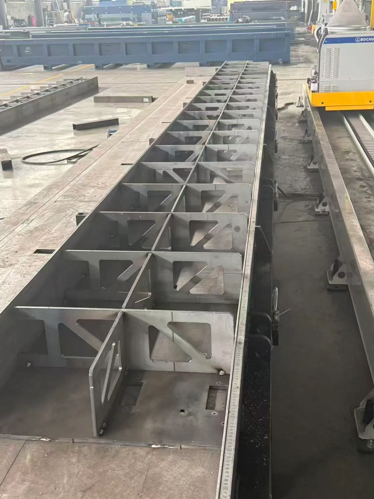
Steel-frame construction · industry reference
Applications & Workflow
Profile processing is relevant to building frames, fabricated supports, equipment structures and other heavy steel assemblies. The useful production route begins before cutting: identify stock grade and section, match it to the drawing revision and determine the processing datum.
After cutting, preserve member identity through inspection, fit-up, welding and coating. Plan access for the next operation and allow space for long prepared members. The benefit of integrating preparation is strongest when the fabrication team can use the completed features without repeating layout work.
For example, a channel support with several slots is primarily a feature-location and orientation task. A beam end with a cope and weld preparation adds access, separation and joint-geometry constraints. Both are profile work, but they should not be evaluated using the same simple straight-cut sample. The appropriate machine configuration follows the difficult detail that appears repeatedly in the workload.
A profile line needs a workshop plan that includes stock queues, loading equipment, processing clearance and discharge. Check crane coverage and lifting access against the heaviest intended member. Foundation requirements and support alignment should follow the selected layout and installation documentation.
Training should cover section setup, member orientation, datum selection, program verification, support sequencing and inspection of the first connection detail. Coordinate the project through installation and training and define ongoing assistance through service support.
For a transported line, the installation sequence must also restore the intended relationship between the feed, cutting and discharge sections. Reference information, module identification and alignment requirements belong with the installation documents. The production and delivery process explains how these configured sections and their accessories stay traceable through shipment.
Technical Resources
Request an HR configuration sheet, section-capacity drawing, equipment layout and utility requirements. For a technical review, provide the complete member drawing together with an enlarged connection detail and the proposed data file.
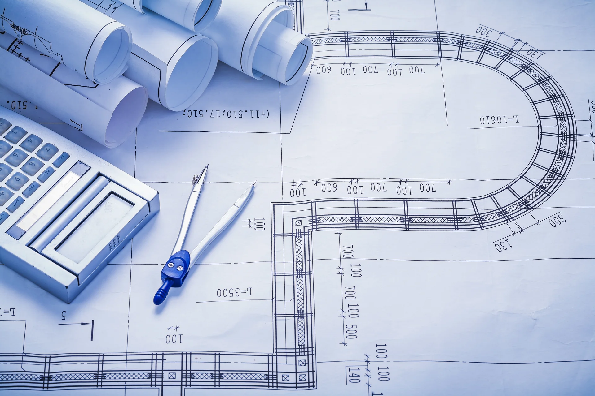
Engineering drawings · reference
Why should the imported profile be reviewed before cutting?
A structural model and a cutting toolpath serve different purposes. Incorrect section recognition can create unintended inner and outer paths or misinterpret the root geometry. A useful program review checks the recognized section, reference face, feature orientation and cut sequence against the drawing. File import succeeding is only the first step; the generated path must describe the required physical preparation.
The process may share laser technology, but heavy open sections need different access and handling. A tube machine’s diameter range does not establish its suitability for a large H-beam or channel.
Can laser cutting replace drilling for all structural holes?
The required hole process and finished condition depend on the project specification and connection design. Identify which holes may be thermally cut and which require drilling, machining or a separate finishing step before evaluating the production route.
That depends on the section, head access and support arrangement. Provide all features on the drawing so a process sequence can identify any repositioning or inaccessible areas.
Is the catalog maximum section also the maximum bevel capacity?
No. Section fit, straight-cut capacity and bevel capability are different limits. An inclined cut changes the required access and material path; confirm it using the actual flange or web detail.
Visual reference · to be replaced
Does profile measurement remove incoming-stock requirements?
No. Any measurement or compensation system operates within limits. Stock straightness, twist and dimensional variation still need to suit the proposed process and finished-part requirement.
Send section sizes, member lengths and masses, material grades, web and flange thicknesses and connection drawings. Identify critical holes, bevels, datum requirements and the intended fabrication route. Include workshop dimensions and material-handling equipment so the cutting proposal can be developed around the complete member flow.