Handheld laser welding a sheet-metal sample
Handheld laser welding · sample demonstration
CHENDA / Joining technology

Welding Machines & Systems

Product Overview

A clean cabinet corner, a sealed enclosure and a load-carrying frame place different demands on a welding machine. The cabinet needs a controlled visible bead; the enclosure needs continuity through starts and stops; the frame needs the specified weld section where loads transfer between members. CHENDA’s welding range brings together handheld laser welding, automatic platform laser welding and robotic laser or MIG/MAG systems for these different tasks.

Choose flexibility for a changing job mix, programmed motion for recurring seams, or a robot for changing tool angles around an assembly. Then connect the equipment with the preparation, workholding and inspection that make the finished part useful. The result to target is an acceptable assembly ready for its next operation, not simply a fast-moving welding head.

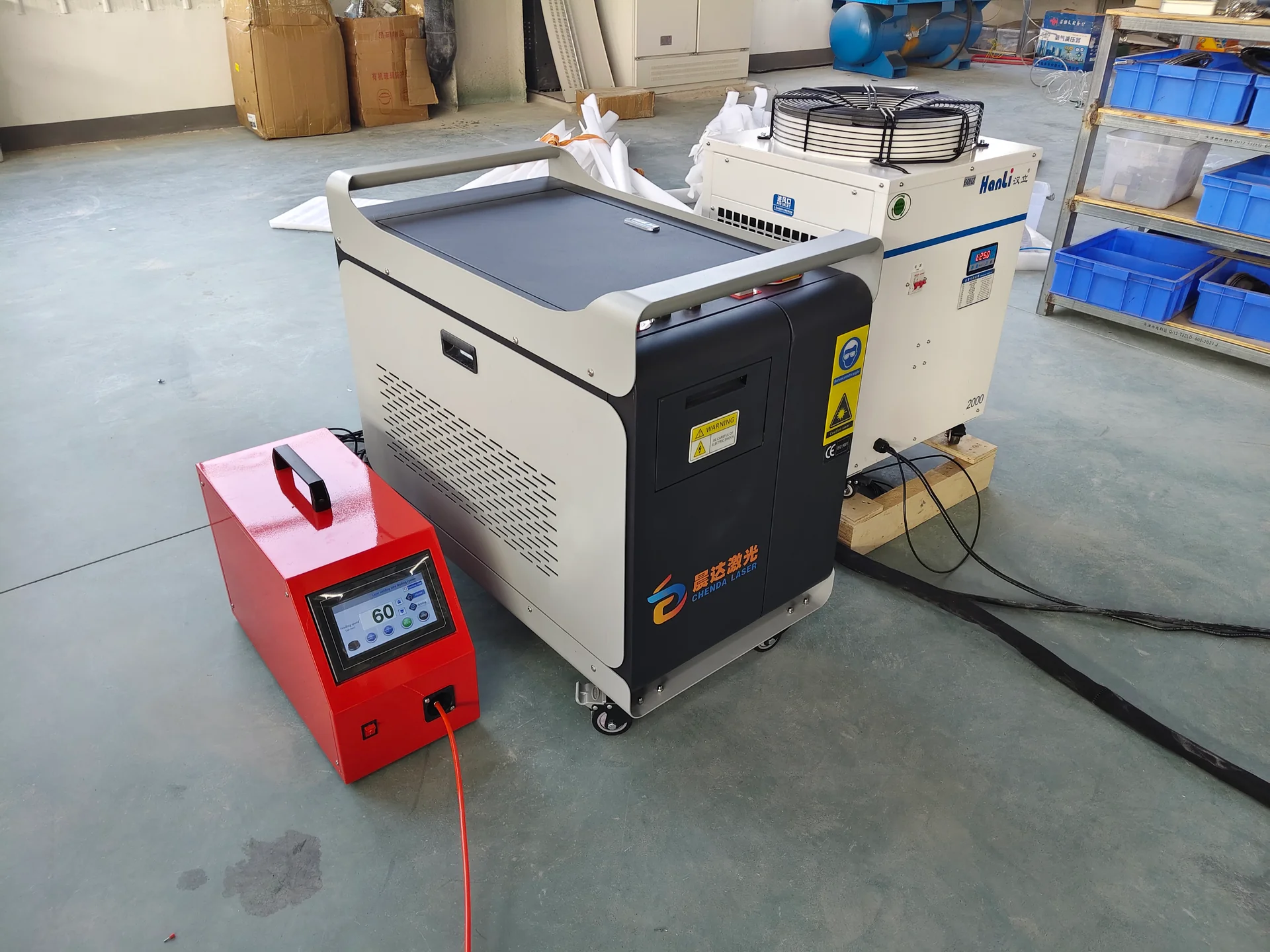
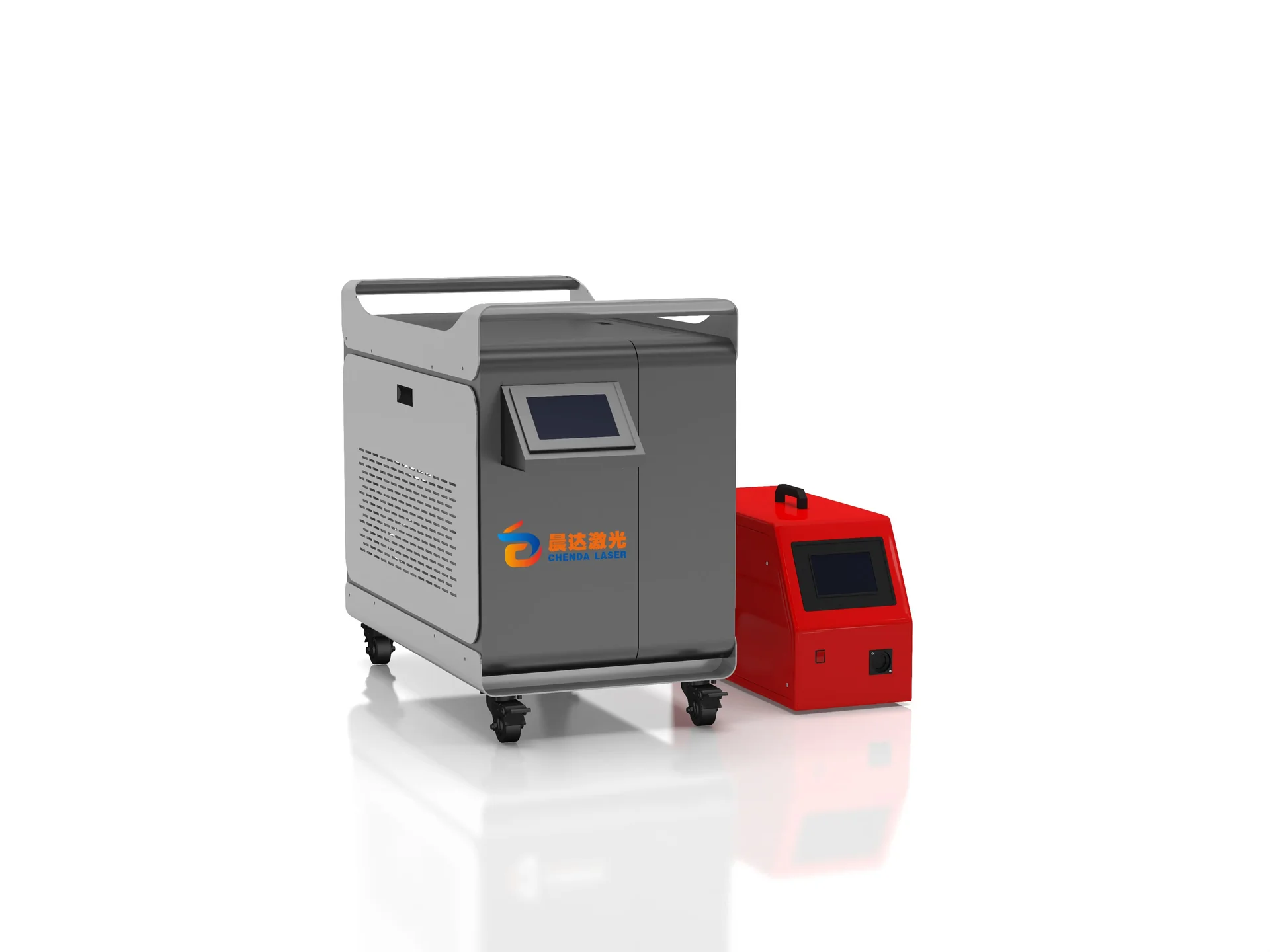
CHENDA handheld laser welding cabinet with a red wire feeder and a Hanli cooling unit.
Laser source, wire feeder and cooling package

Materials & Capabilities

Steel, stainless steel and selected aluminum alloys are the principal material groups for evaluation. Compatibility depends on the exact grade, coating, joint design and welding procedure. Galvanized parts, dissimilar metals and highly reflective materials need a dedicated process review rather than selection from a general material list.

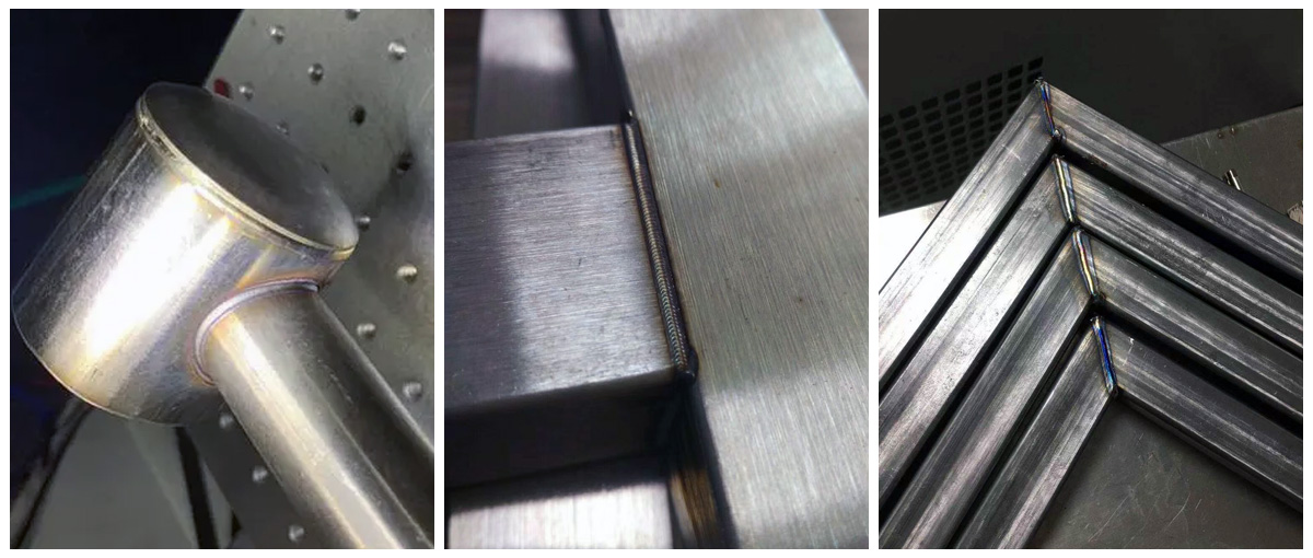
Third-party handheld-laser-welding samples showing a round-tube connection, a rectangular joint and welded mitered tube-frame corners
Tube joint examples · laser-welded samples · Suntop Laser
Joint or production requirement Route to evaluate Main condition
Varied sheet-metal corners and accessible short seams Handheld laser welding Operator access, controlled fit-up and a suitable laser work area
Repeated straight, contour or circular seams Automatic platform laser welding Repeatable part location and sufficient axis travel
Multiple seams on different faces Robotic laser welding Head access, stable joint position and laser containment
Wire-filled fillets and fabricated frames Robotic MIG/MAG welding Qualified wire, gas, arc program and torch approach
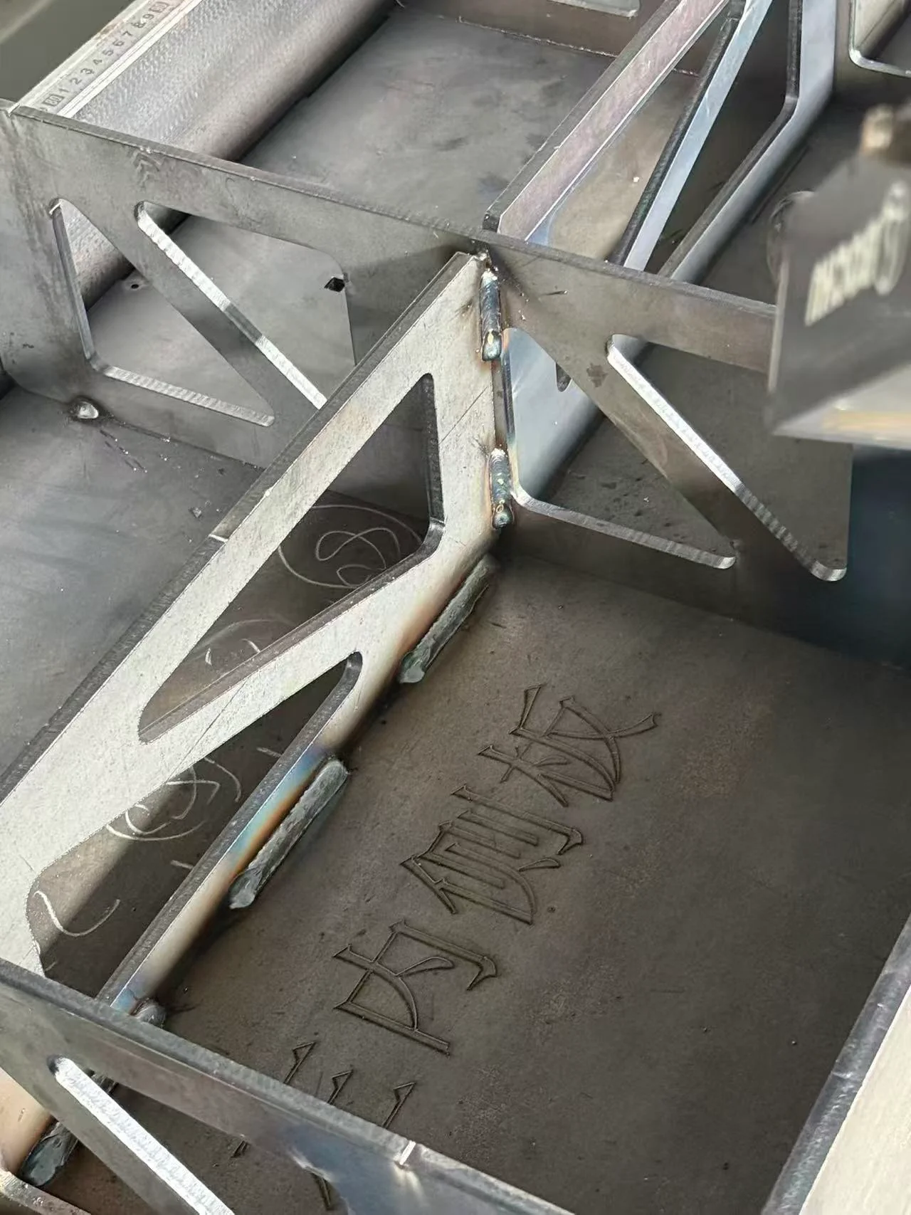
Steel assembly with triangular stiffeners and visible weld joints.
Inspect the joint section as well as the visible weld

Read the joint before choosing the machine

A butt joint brings two edges together; edge mismatch and gap control determine how reliably the process reaches the intended section. A lap joint adds an interface beneath the visible surface, so a smooth top bead can hide inadequate joining below. A corner joint exposes an edge that may melt differently from the adjacent face. A fillet connects intersecting surfaces and must achieve the required weld geometry, rather than merely cover the meeting line.

This distinction matters when comparing offers. Two machines demonstrated on sheet of the same thickness may have produced very different joints. Identify both component thicknesses, access from one or both sides and the required welded section. An attractive bead alone does not establish load capacity, corrosion performance or leak tightness.
Features & Engineering

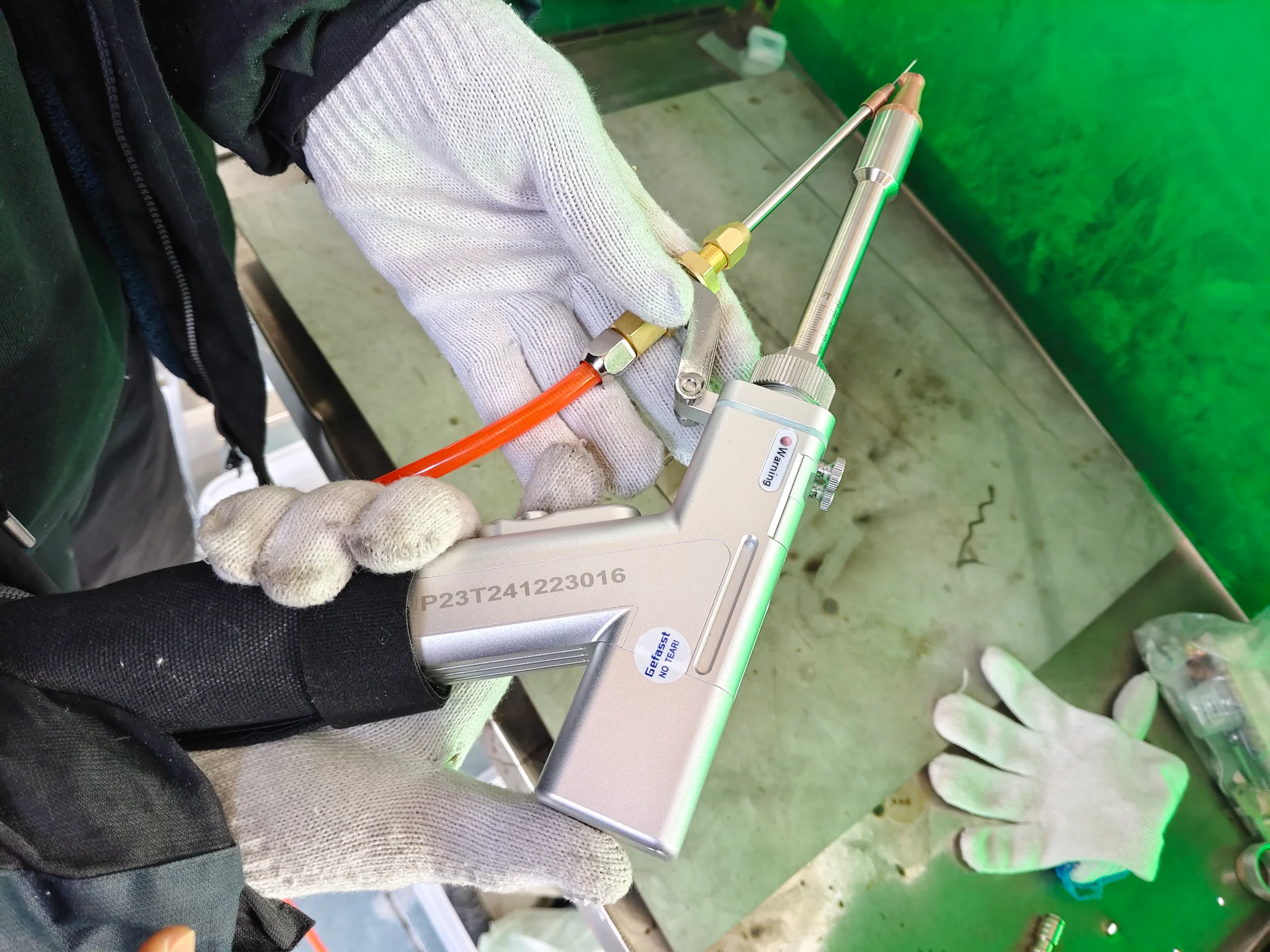
Handheld laser welding head showing the nozzle, wire guide and attached cable assembly.
Head and filler-wire relationship

Put motion and joining technology together

Compact gray CHENDA laser welding cabinet with an external red wire feeder.

Handheld laser welders suit frequent part changes where the operator can follow the seam. Head balance, cable routing, nozzle access and wire-feed alignment influence practical usability.

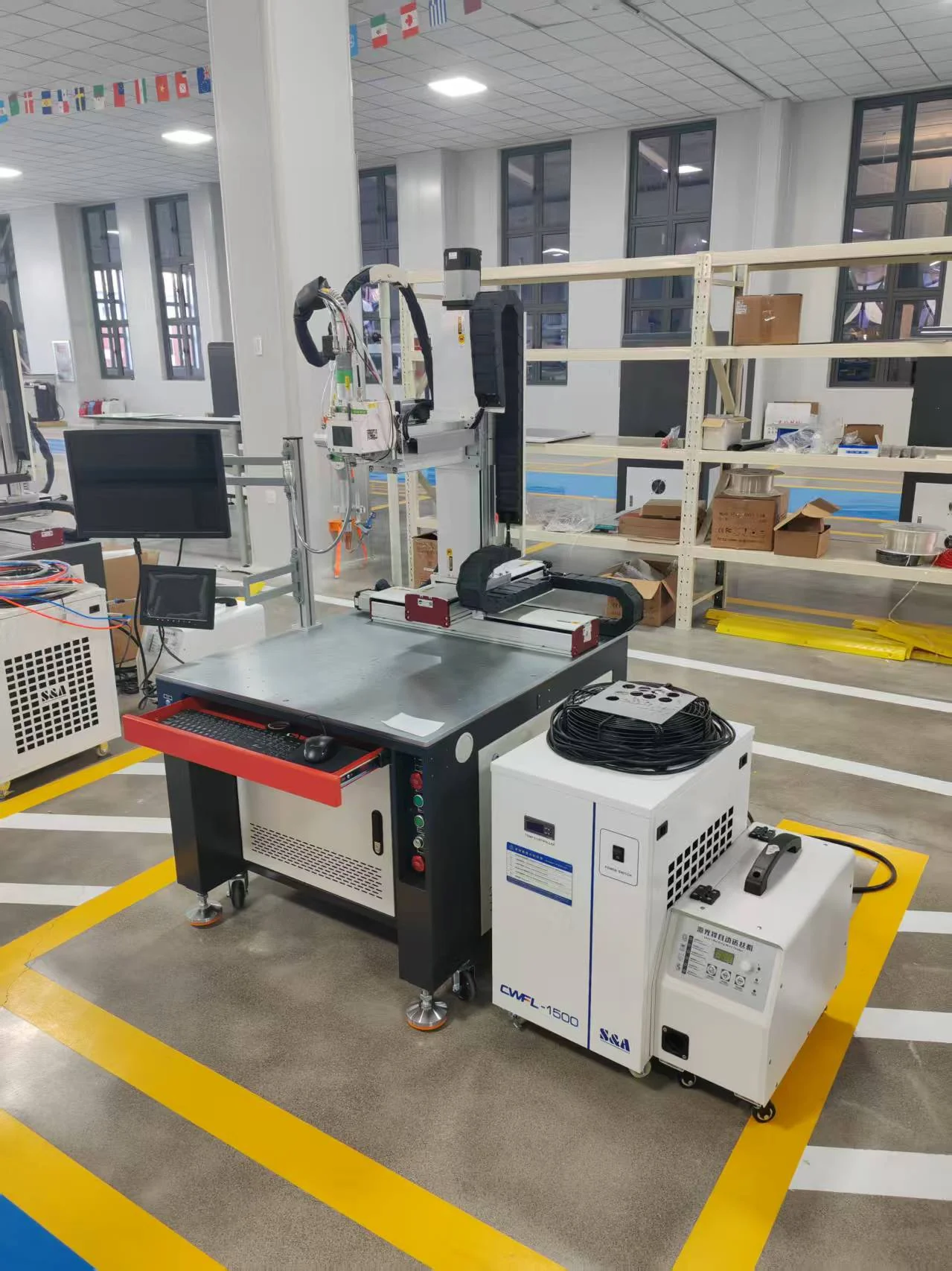
Automatic laser welding workstation with a positioning table, welding head, monitor and external chiller.

Automatic laser welding machines combine controlled motion with a fixture. Their value comes from repeating the relationship between beam, seam and travel speed, especially where several parts share a common datum.

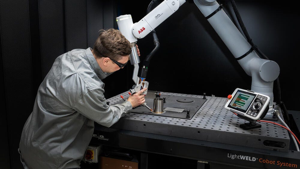
Operator teaching an IPG LightWELD laser-welding cobot path on a fixture table
Laser welding cobot · path teaching reference · IPG Photonics

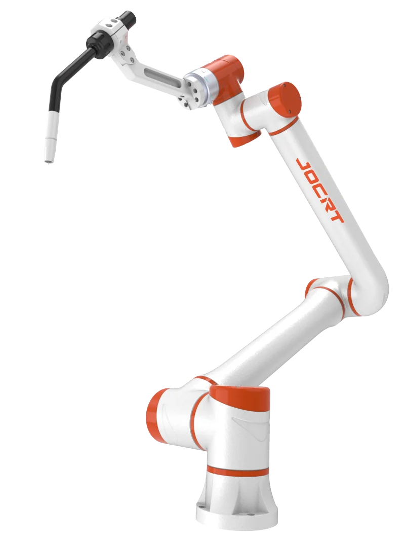
Robotic welding systems address changing torch angles and multi-face assemblies. Effective coverage depends on the complete tool, fixture and workpiece—not the arm’s nominal reach alone.

Control the factors that create rework

For laser welding, fit-up and beam position are central. For MIG/MAG, wire delivery, gas coverage and contact-tip condition also strongly affect the arc. In both cases, sensible clamping and weld sequencing help keep the cooled assembly within dimensional requirements. Automation repeats the selected process; it cannot remove an unstable input condition by itself.

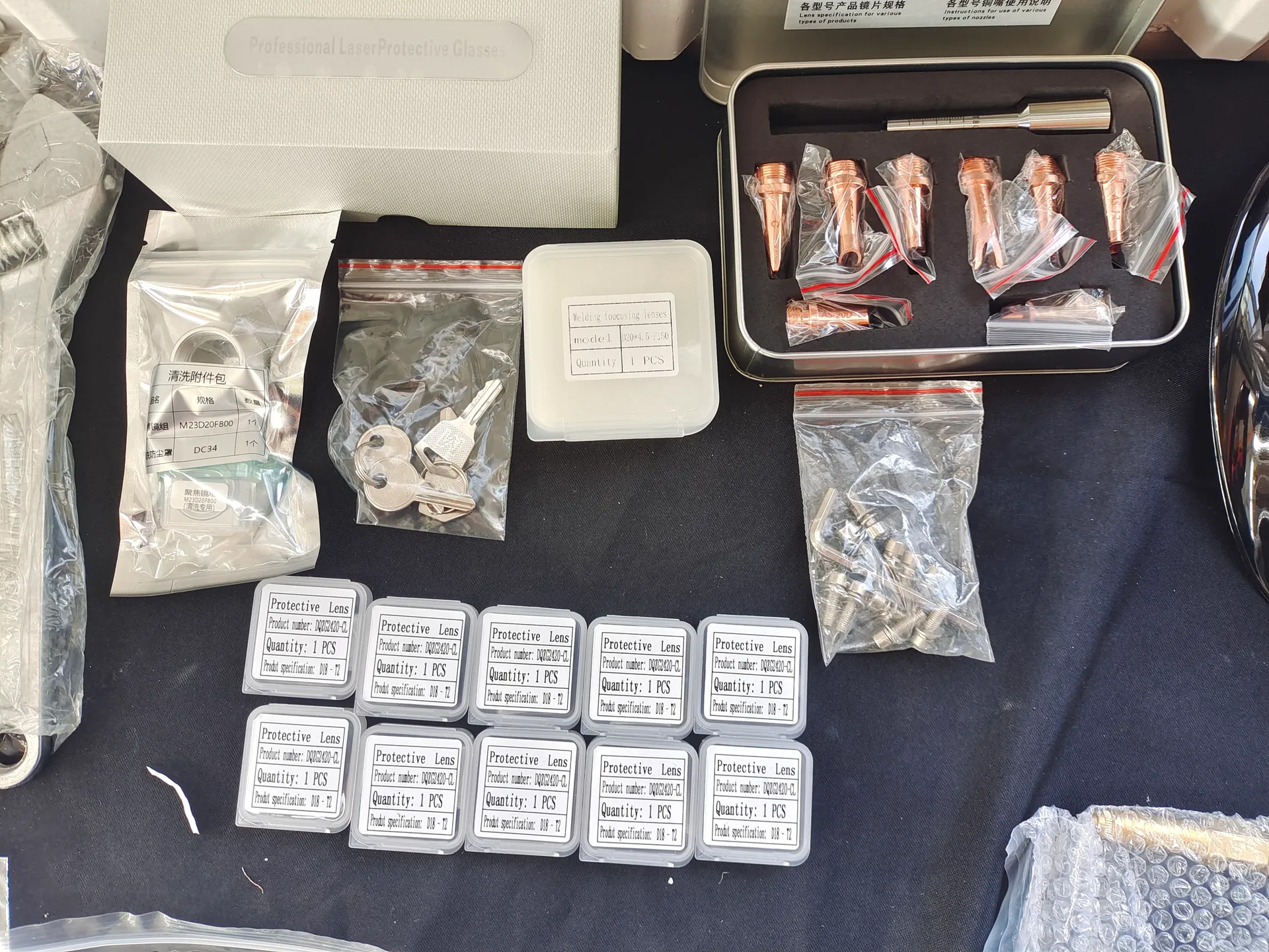
Copper welding nozzles, packaged protective optics and accessories arranged on a work surface.
Nozzles and protective optics
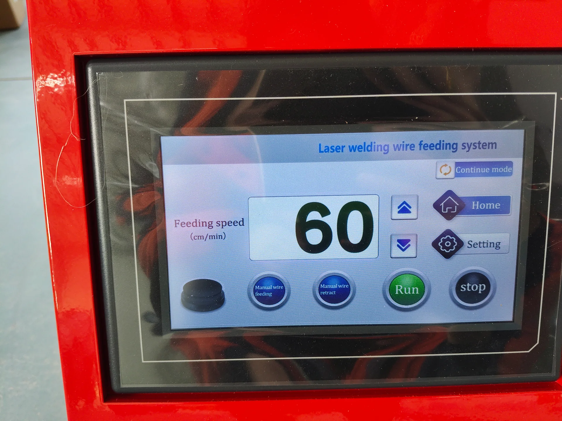
Touchscreen on a red laser welding wire feeder showing feeding controls.
Wire-feed control
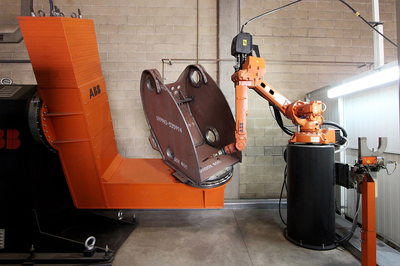
ABB welding robot and positioner holding a heavy fabricated steel housing
Arc-welding cell reference · Ana 2016 · CC BY-SA 4.0

Balance energy, motion and added metal

At a constant laser output, slower travel supplies more nominal energy along each unit of seam length. That relationship helps explain why a paused hand or a slowing programmed corner can behave differently from a straight run. The absorbed energy also changes with the material, focal condition and joint geometry, so power divided by travel speed is not a complete welding recipe.

MIG/MAG adds another relationship: wire is both electrode and filler. Wire-feed rate, arc behavior and travel speed jointly influence deposited metal and heat. A large bead can still have poor fusion; increasing deposition without addressing the arc and joint geometry may add grinding work instead of useful weld section.

Technical Specifications

The comparison below defines the information needed to select an equipment route. Exact capacities belong to the proposed configuration and tested joint.

Automatic laser welding workstation with a positioning table, welding head, monitor and external chiller.
Specification Handheld laser Platform laser Robotic laser Robotic MIG/MAG
Energy setting Optical output, W Optical output, W Optical output, W Current, A; voltage, V; arc mode
Processing envelope Head access and cable length, m Axis travel and fixture clearance, mm Reach, mm; tool payload, kg; head orientation Reach, mm; tool payload, kg; torch orientation
Material capacity Grade, thickness and joint, mm Grade, thickness and joint, mm Grade, thickness and joint, mm Grade, joint preparation and weld size, mm
Filler delivery Optional or required by joint Matched to programmed path Coordinated with robot motion Consumable electrode wire; diameter, mm
Production measure Completed acceptable parts per operator shift Full load-to-unload cycle, s Full cell cycle, s Full cell cycle, s; arc duty at stated conditions
Quality reference Approved sample and procedure Approved sample and fixture Approved sample and cell program Applicable welding procedure and inspection criteria

Laser optical power is different from total electrical demand. Similarly, a MIG/MAG current rating needs its duty-cycle and temperature conditions. Compare like-for-like configuration data rather than treating either headline number as a universal thickness rating.

Samples & Demonstration

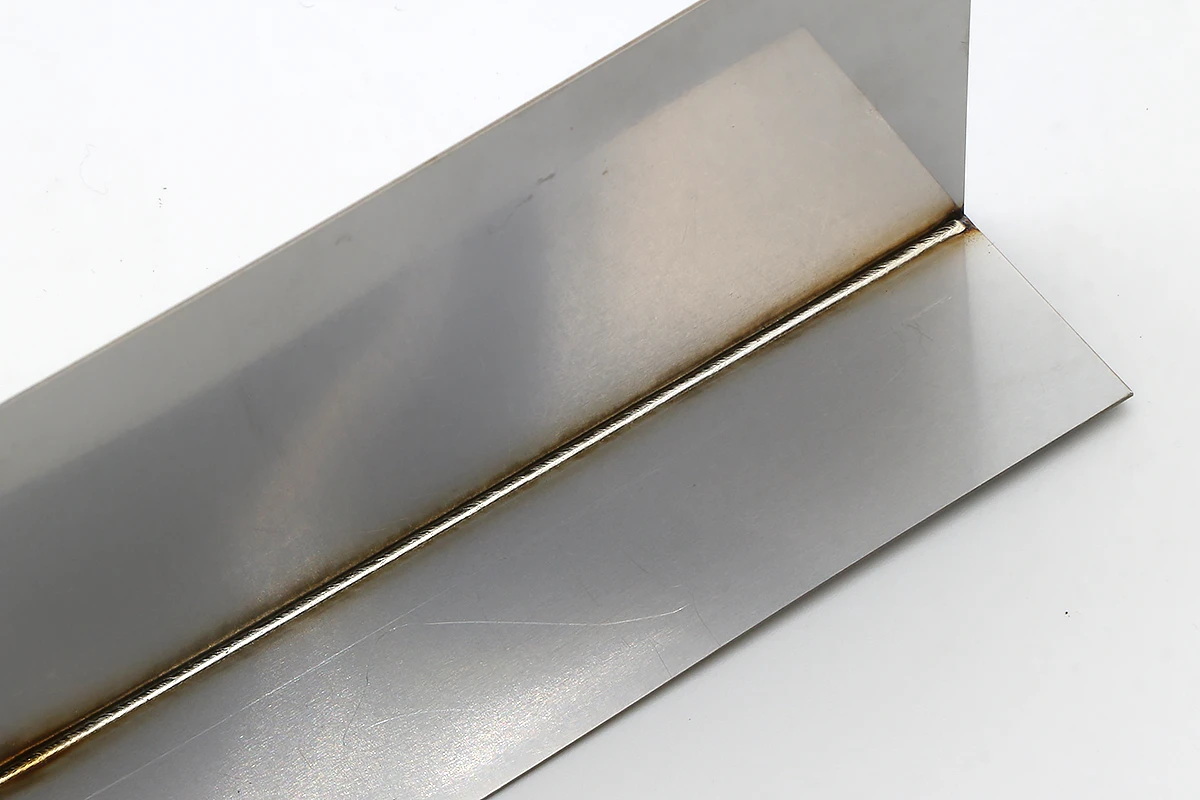
Select sample joints that represent the production risk. A visible stainless corner tests finish and distortion; a closed box adds start/stop and access challenges; a tube frame tests fit-up and torch clearance; a fillet weld tests the required weld section.

Third-party laser-welded sheet-metal inside-corner sample with a continuous visible weld seam
Laser-welded thin-sheet corner reference · smartDIYs
Observed result Possible process issue to investigate Useful evaluation
Attractive surface but inadequate joint section Energy placement, preparation or access Examine the joint section using the agreed inspection method
Shape changes after unclamping Heat sequence, restraint or incoming-part stress Compare the cooled, released assembly with its drawing
Variable bead along a repeated seam Fit-up, travel, focal position or wire delivery Connect the variation with its location on the part
Defect concentrated at a start or stop Process timing or termination behavior Inspect the transition separately from the steady seam

These are investigation routes, not diagnoses from appearance alone. A useful demonstration connects a specific defect with a controlled process change and the resulting part quality.

Request a demonstration using the intended material grade and thickness. Include normal joint variation, not only a perfectly prepared coupon. Review the cooled dimensions and the specified inspection results alongside the surface appearance. For an automated system, include loading, clamping and unloading in the cycle demonstration.

Configuration & Options

Build the configuration around the selected process. Laser systems require a matched source, head, controls and cooling arrangement; a wire feeder may be needed for the joint. MIG/MAG cells require a compatible power source, feeder, torch, gas system and return-current path.

Fixture plates, rotary positioners, additional motion, process viewing, extraction and production data interfaces can be discussed where they solve a defined need. Their inclusion and compatibility are established in the quotation. A robot package and a complete production cell have different delivery scopes.

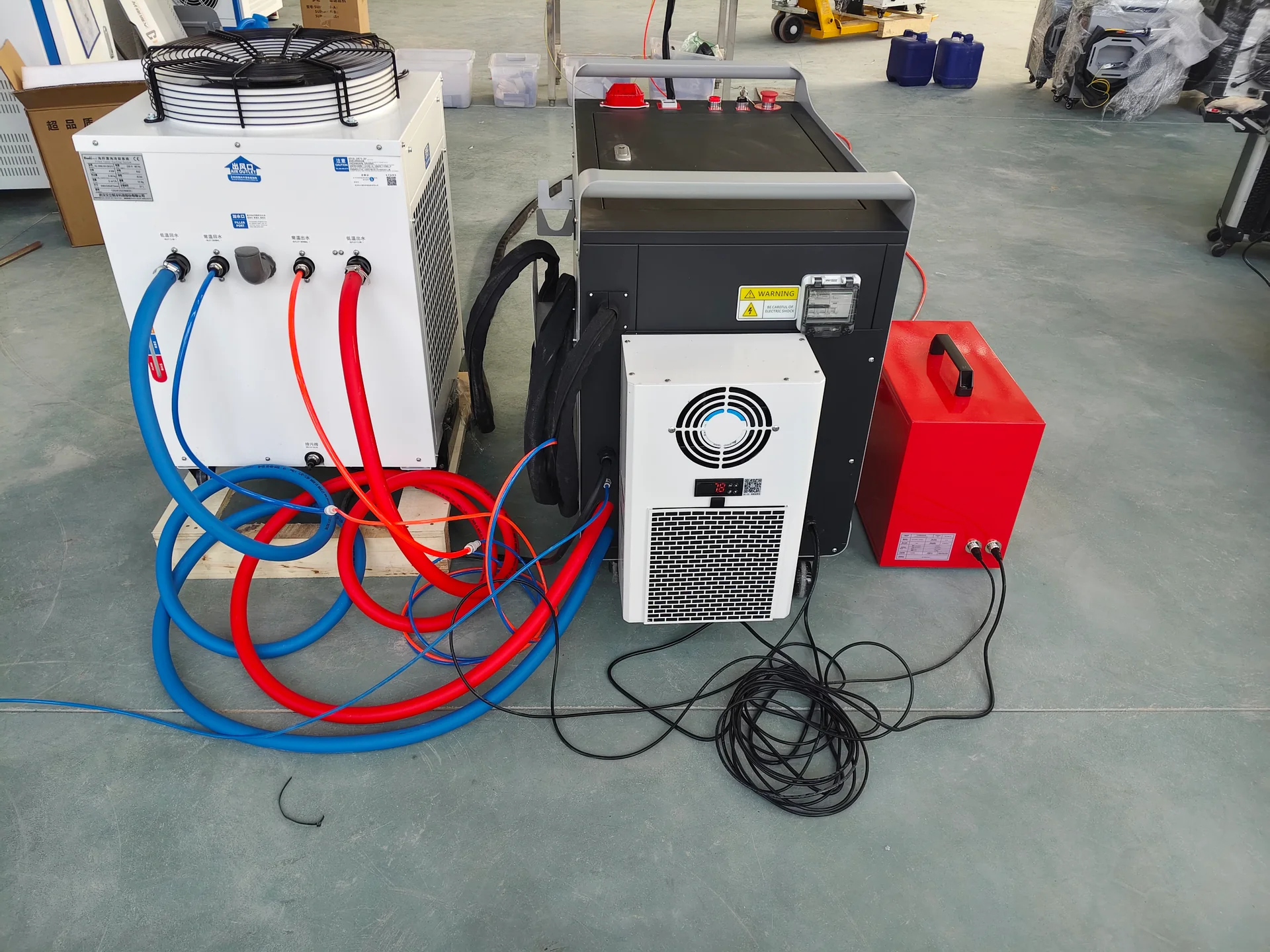
Rear view of a laser welding cabinet and chiller with connected cooling hoses and cables.
Cooling connections
Handheld laser welding head showing the nozzle, wire guide and attached cable assembly.
Head and wire guide

Applications & Workflow

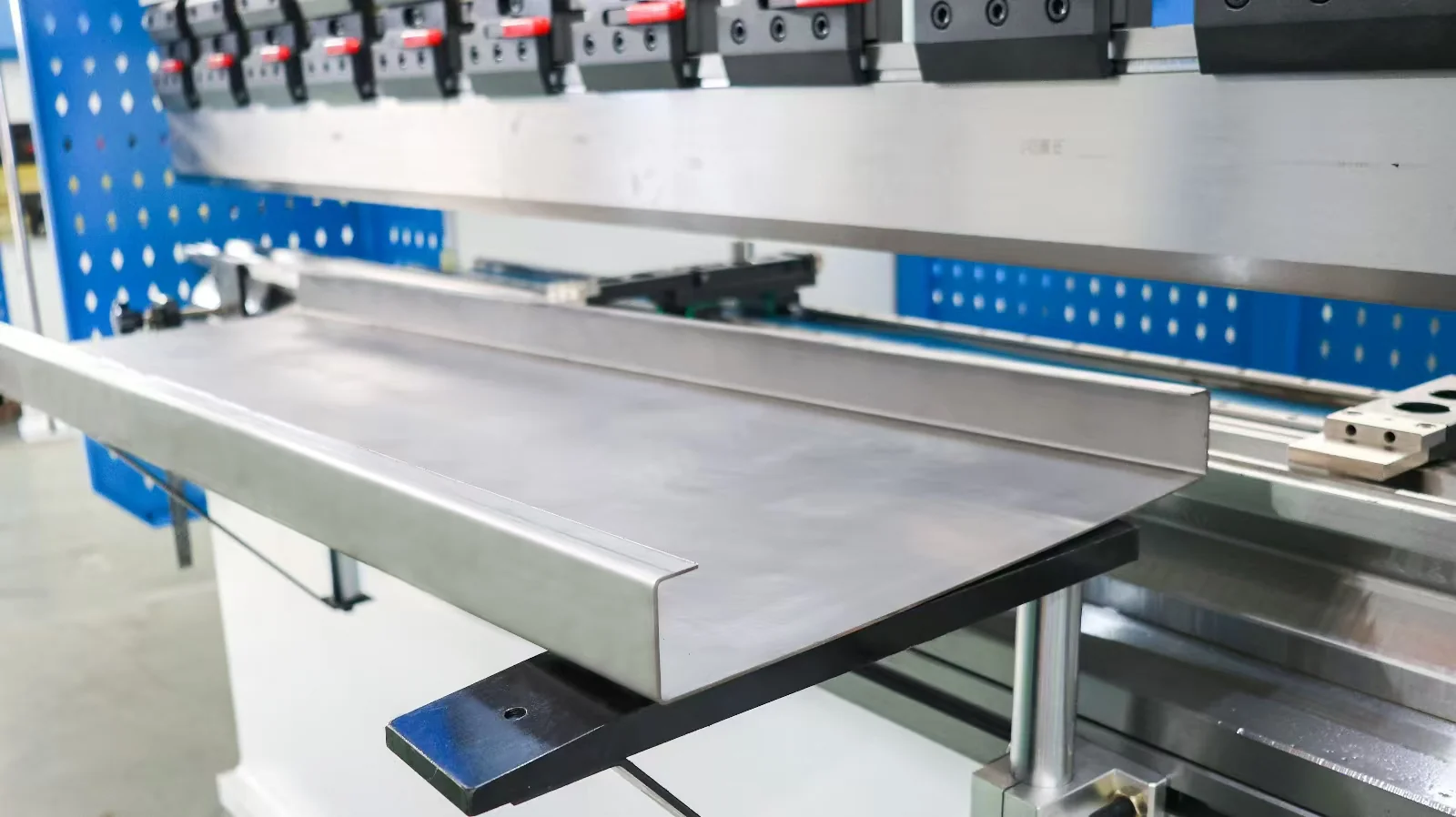
A practical sheet-metal route is cutting, edge preparation, bending, fit-up, welding and final surface work. Accurate blanks and bends reduce the correction needed at the welding station. Keep protective film, oil and coating residue outside the prepared weld area as required by the process.

For frames, establish datums before welding and plan the seam sequence around access and distortion. Inspect after release from the fixture: a part that looks correct while heavily clamped may move when unloaded.

Steel assembly with triangular stiffeners and visible weld joints.
Fit-up and weld access · reference

Three practical production arrangements

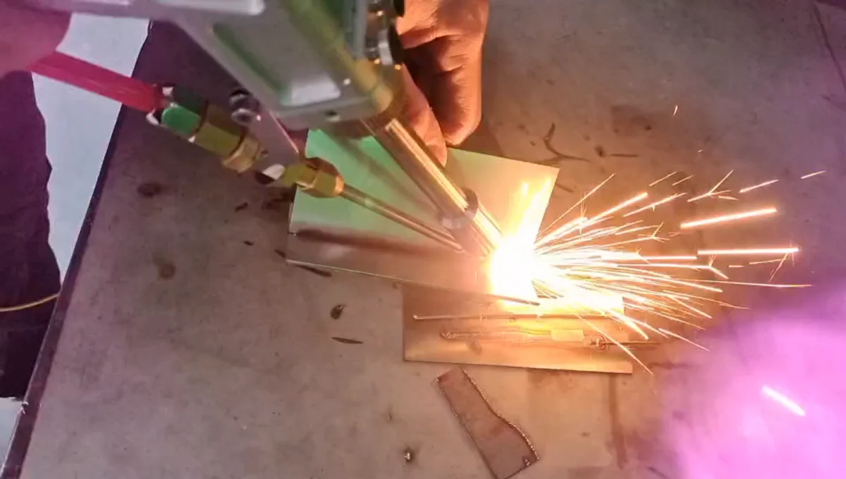
Handheld laser welding a sheet-metal sample
Flexible handheld process

A workshop producing varied covers and corners: a handheld station can keep fixture investment modest while accommodating different seam lengths. A supportive worktable and repeatable edge preparation reduce operator effort. The bottleneck may be part positioning rather than laser-on time.

Automatic laser welding workstation with a positioning table, welding head, monitor and external chiller.

A recurring family of small enclosures: a platform can use a dedicated locating fixture and a repeatable contour program. Interchangeable locating details may accommodate a controlled size family. Loading errors and corner transitions deserve as much attention as straight-seam speed.

ABB welding robot and positioner holding a heavy fabricated steel housing
Multi-face robotic arc-welding reference · Ana 2016 · CC BY-SA 4.0

Frames with welds on several faces: a robot can address changing tool angles, with a positioner where justified. The cell should be organized around the assembly sequence, torch/head access and part handling. A laser route and an arc route may require substantially different fixtures even for a similar frame outline.

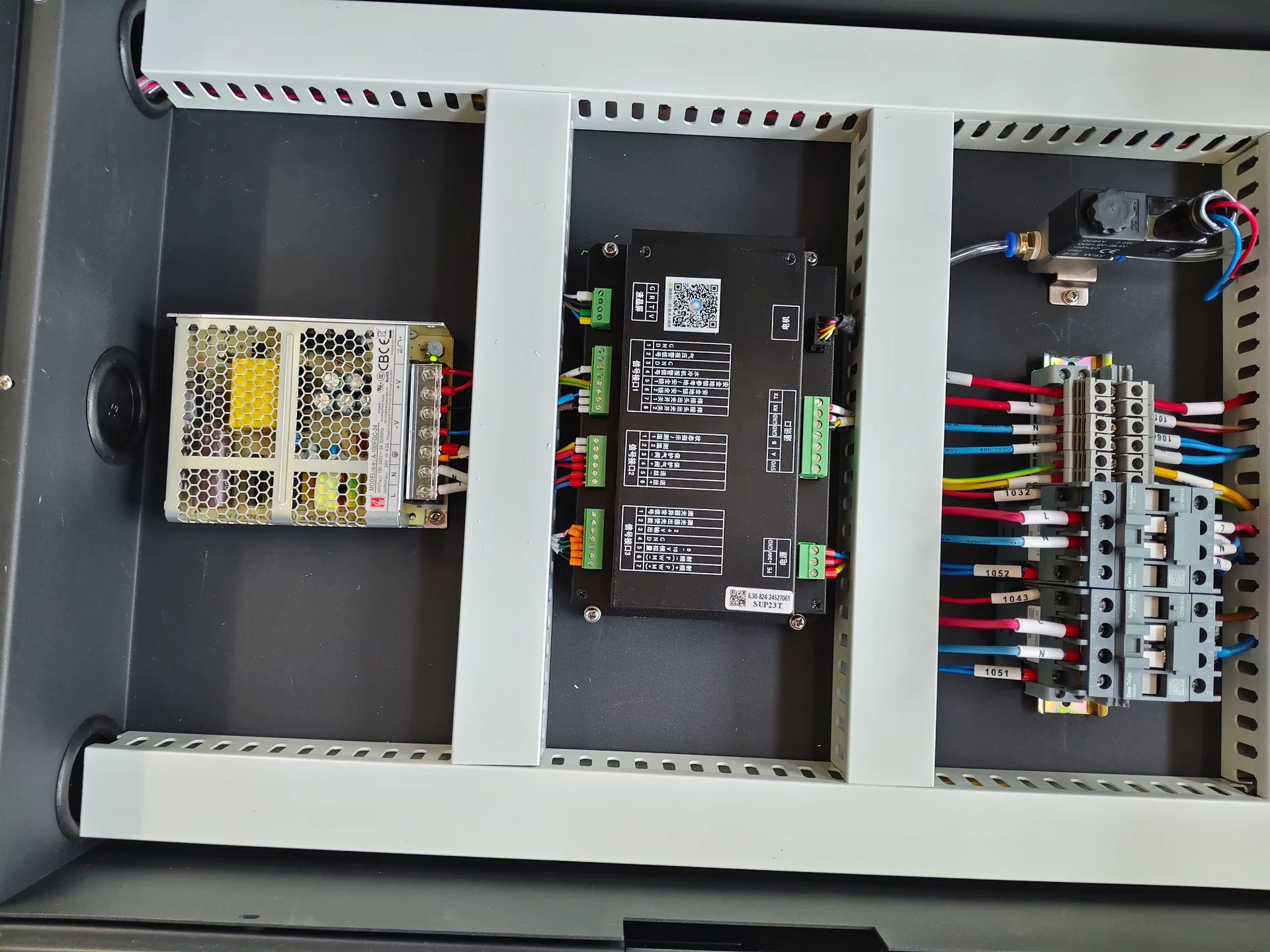
Laser welding control cabinet showing the controller, power supply and labeled electrical connections.
Equipment electrical integration

Installation & Support

Prepare power, gases, extraction, cooling clearance and workpiece handling for the selected system. Laser installations require suitable controls for beam exposure and reflections. Arc cells require protection from arc radiation, spatter and fumes. Robot motion and positioners introduce additional access hazards.

Training should connect the machine controls with actual production tasks: setup, sample approval, consumable inspection, program recovery and routine maintenance. Confirm the installation and training scope for your order.

Technical Resources

The most useful technical package links a machine configuration to a joint drawing. It identifies the source or power supply, head or torch, motion arrangement, consumables and utilities, then records the material and procedure used for the sample. For an automated cell, a fixture concept and operating sequence make the quoted scope tangible.

Jinan Chenda Tech Co., Ltd. is based in Jinan, Shandong, China. The company’s quality-control approach explains how equipment identification, functional checks and sample evidence connect; its production and delivery process covers the handover information needed at the destination. These records support a welding project more directly than a general maximum-capacity claim.

Technical drawings with a calculator and drafting compass
Joint and process review · visual reference

Product FAQs

Handheld laser welding head showing the nozzle, wire guide and attached cable assembly.
JOCRT collaborative robot arm fitted with an arc welding torch.
Visual reference · to be replaced

Should I choose laser or MIG/MAG welding first?

Choose the joining process from the material, joint and required result, then choose how to move the tool. A robot can carry either process, but that does not make their gap tolerance, filler requirements or heat distribution identical.

Automatic laser welding workstation with a positioning table, welding head, monitor and external chiller.

When does automation become useful?

When a repeatable fixture, stable parts and a recurring seam pattern can support it. Compare total cycle time and changeover effort with your batch mix. A short welding time alone does not establish a productive automated cell.

Steel assembly with triangular stiffeners and visible weld joints.
Visual reference · to be replaced

Can one thickness table cover all welding systems?

No. A butt joint, lap joint and fillet require different weld geometry. Material grade, preparation, penetration target and one-sided or two-sided access change the process window.

Third-party laser-welded sheet-metal inside-corner sample with a continuous visible weld seam
Visible-seam reference · smartDIYs

Will laser welding eliminate finishing?

It can reduce finishing on suitable joints, but the result depends on bead shape, discoloration, surface requirements and any coating applied afterward. Define the acceptable finished surface on the sample.

Handheld laser welding head showing the nozzle, wire guide and attached cable assembly.

Can the same gas serve every process?

Do not assume so. Select shielding gas for the welding process and material. Compressed workshop air is not a general substitute for welding shielding gas.

Request a Quote

Send the material grade, thickness, joint detail, part dimensions and normal batch size. Add your required weld appearance, inspection method and production target. If you already use a welding process, explain the limitation you want to address—distortion, finishing, operator workload, cycle time or difficult access.

Technical drawings with a calculator and drafting compass
Start with the joint drawing