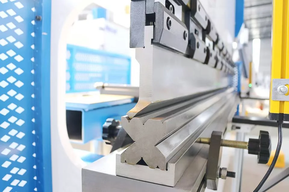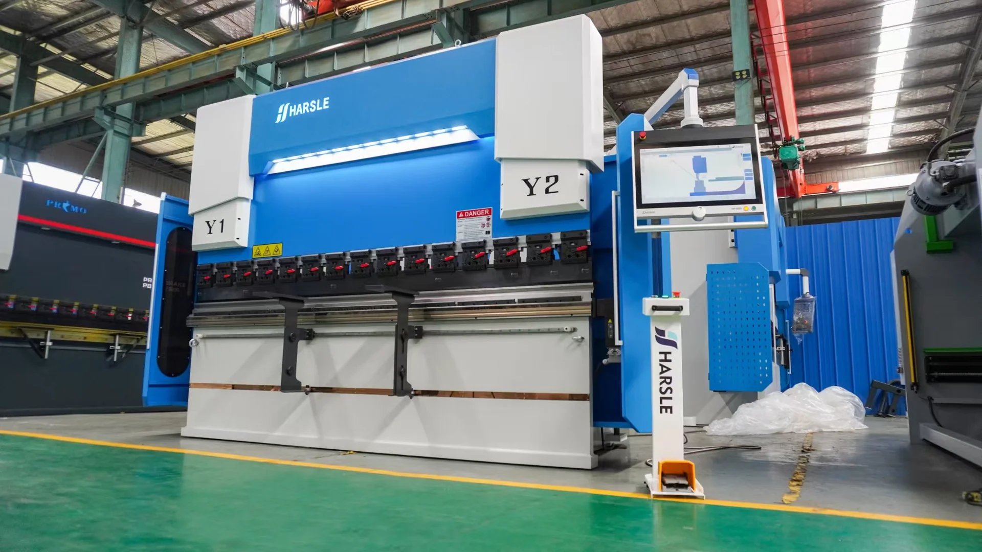
Blue and white HARSLE CNC press brake with a side-mounted controller in a workshop.
Bending workshop · third-party equipment reference
CHENDA / Sheet metal forming

Press Brakes for Sheet Metal Bending

Product Overview

Turn a flat blank into a cabinet, bracket, tray or formed panel with a press brake selected around the finished part. Bending force matters, but so do tool clearance, gauging, bend sequence and the operator’s ability to handle the work between strokes.

CHENDA’s press-brake range covers three equipment directions: torsion-bar machines for straightforward forming, electro-hydraulic CNC machines for programmable multi-bend work, and electric machines for applications that benefit from servo-driven motion. Compare the routes below, then send the drawings that define your production.

Formed sheet-metal channel resting on the front supports of a press brake.
Formed channel · bending reference
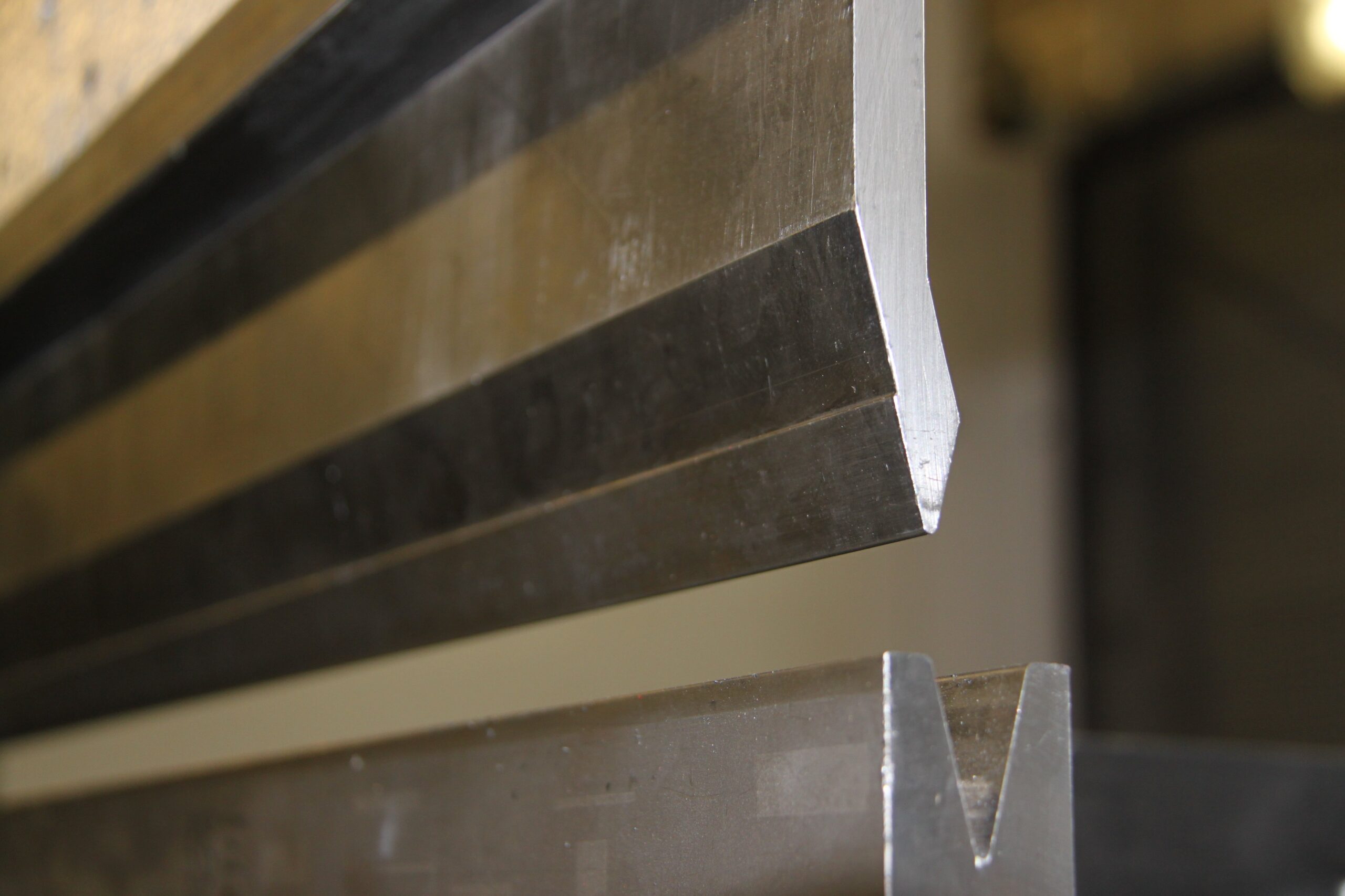
Close-up photograph of press brake punch and V-die tooling
The tool pair defines the bend · Contour (uploaded by Jasper84) · CC0 1.0

Materials & Capabilities

Press-brake applications include carbon steel enclosures, stainless steel covers, galvanized channels and aluminum brackets. Material grade, temper, grain direction and the required inside radius affect whether a bend can be formed without cracking or unacceptable surface damage.

Air bending offers flexibility because the punch penetrates into a die opening without fully seating the material against the tool faces. The resulting angle depends on penetration and springback. Bottoming, coining, hemming and special forming require their own tooling and force assessment; an air-bending capacity must not be carried over to those operations.

A useful part review includes both the flat pattern and finished geometry. A short flange may demand a smaller die opening, increasing force. A deep box may need taller tooling and more clearance even when its material is thin.

The same sheet thickness can produce very different jobs

Consider three design examples: a narrow mounting angle, a full-width cabinet door and a tray with inward-facing returns. The mounting angle concentrates load over a short tool length. The door introduces a longer loaded span and a large sheet that must be supported as it rises. The tray needs a punch profile and tool arrangement that leave space for the returns and allow the formed part to come out. A machine chosen only from sheet thickness misses these differences.

The inside radius is also part of the finished component. Changing the die opening can change that radius and therefore the bend deduction used in the flat blank. For a cover that must fit over another assembly, a change made at the press brake may require a corresponding flat-pattern revision. Keeping the tooling choice connected to the drawing prevents a correct angle from hiding an incorrect overall size.
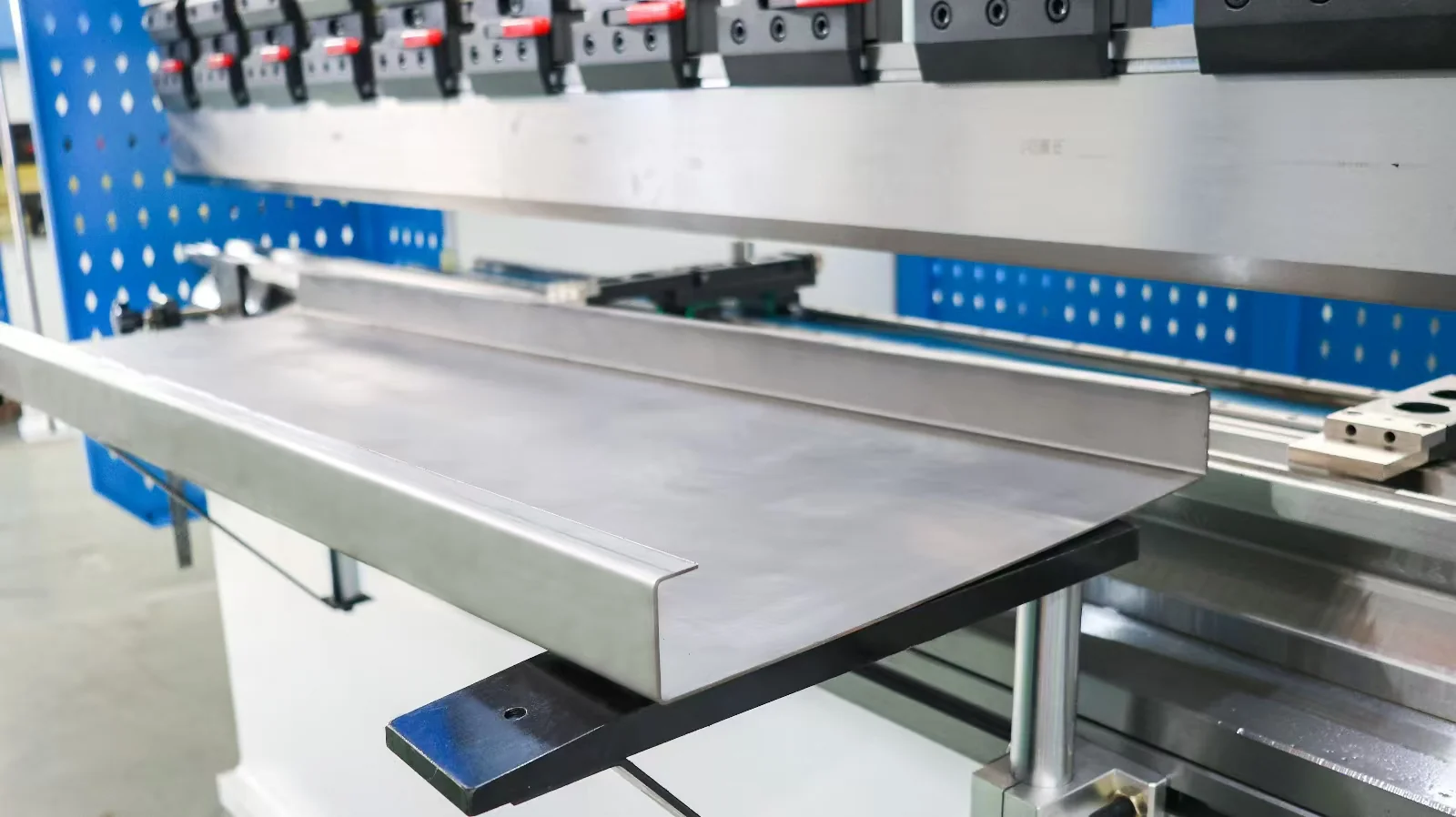
Formed sheet-metal channel resting on the front supports of a press brake.
Channel geometry
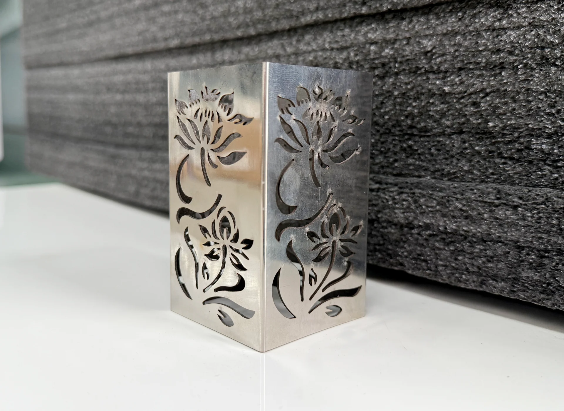
Bent metal panel with floral cutouts across two adjoining faces
Formed sheet sample

Features & Engineering

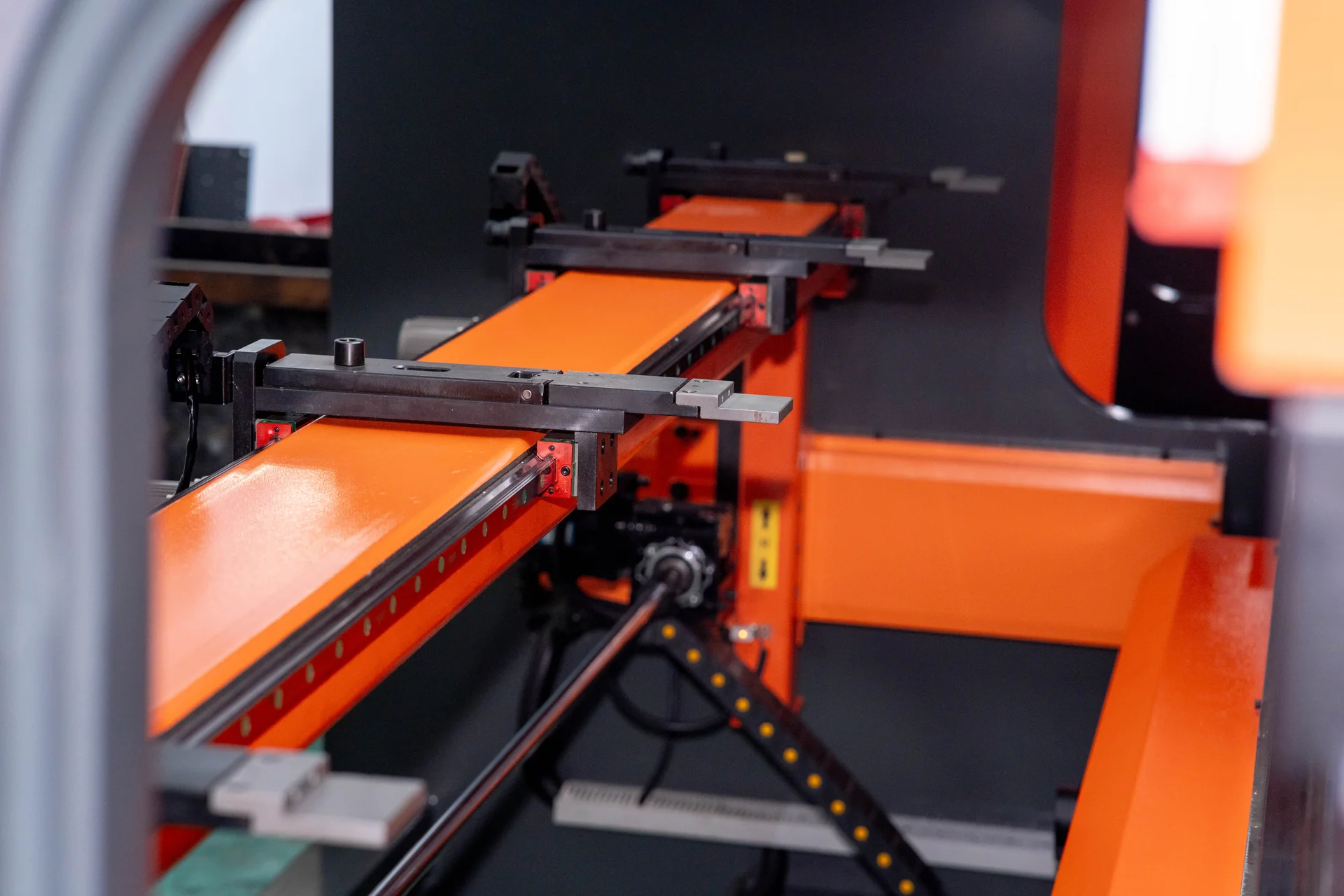
Backgauge beam, guide rails and positioning fingers inside a CNC press brake.
Backgauge detail · reference

Three routes to controlled forming

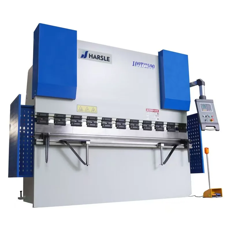
HARSLE press brake with a control panel, front supports and a foot pedal.
Torsion-bar equipment reference
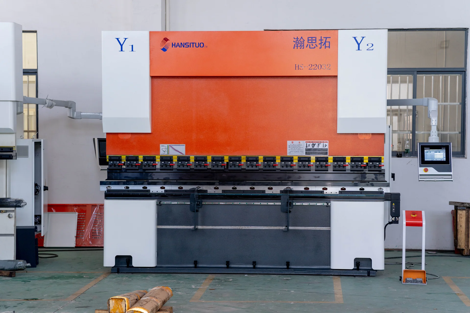
Front view of an orange and white HANSITUO CNC press brake with a side control panel.
CNC equipment reference
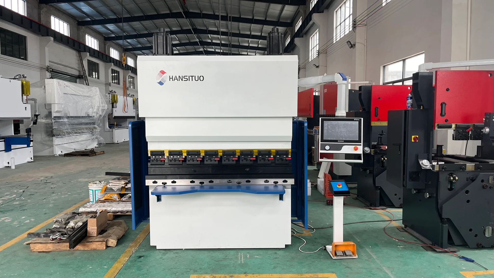
Compact HANSITUO electric press brake with visible upper drive motors and front supports.
Servo-electric equipment reference
Equipment direction Engineering emphasis Production fit
Torsion-bar press brakes Mechanical synchronization with a selected ram-depth and backgauge control package Repeated flanges, brackets and accessible profiles with manageable setup requirements
Electro-hydraulic CNC press brakes Independently controlled hydraulic ram sides, programmable gauging and compensation Mixed part families, long bends and sequences that benefit from coordinated axes
Electric press brakes Servo-electric forming motion and a drive arrangement matched to force and duty Repeated components where cycle motion, workshop conditions and handling are important
Segmented press brake tooling held by a clamp with a red release lever.
Segmented tool clamping
Backgauge beam, guide rails and positioning fingers inside a CNC press brake.
Backgauge positioning

Match the structure to the part

The frame and tooling deflect under load. Crowning compensates for the resulting angle variation along a bend; it does not correct an inaccurate flat pattern or inconsistent material. Backgauge movement reduces repositioning effort, while finger shape and access determine whether the part can actually locate against it.

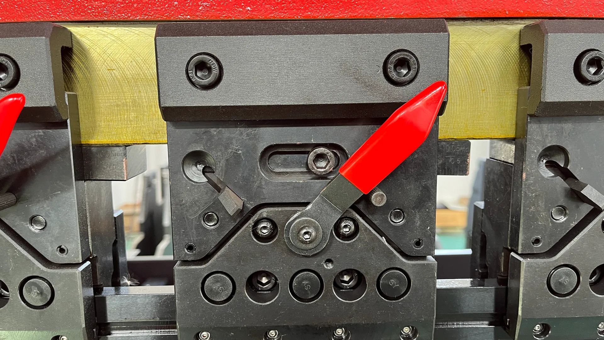
Tool clamping has a direct effect on changeover. Segmented punches can create clearance for box work; compatible quick clamping can shorten tool changes. The tool holder, tool tang and rated load must work as a system.

Three controls, three different jobs

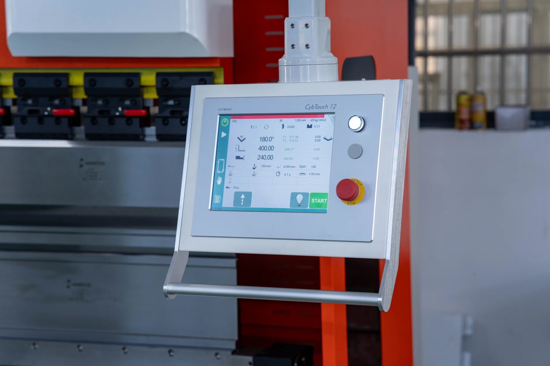
Ram synchronization keeps the two ends of the moving beam coordinated. Crowning changes the compensation profile along the loaded bend. An angle-measurement system, when included, observes the workpiece angle and may support correction through the control. These functions complement one another; none is a substitute for the others.

For example, if the two ends of a long channel have similar angles while the center is more open, load-related deflection is one possible cause. If the whole bend is uniformly more open after a material change, material properties or the programmed penetration may be more relevant. If flange size varies while angle stays consistent, inspect blank dimensions and gauging. Separating these symptoms directs the correction toward the source of the problem.

Cybelec CybTouch control panel mounted on a press brake.
Control interface · reference

Technical Specifications

The catalogue-listed CHD electro-hydraulic family includes four 3,200 mm models with nominal forces from 1,000 to 3,200 kN. See the electro-hydraulic model comparison for the individual values. A model designation alone does not establish the thickness it can bend.

Front view of an orange and white HANSITUO CNC press brake with a side control panel.
Visual reference · to be replaced
Specification Unit or description What it determines
Nominal bending force kN; state the convention if expressed as tons Available forming load under the machine’s permitted loading conditions
Bending length mm Maximum nominal tool working length, subject to the part and tooling
Distance between uprights mm Passage for work that extends into the machine frame
Throat depth mm Clearance for flanges and material reaching around the upright
Ram stroke and daylight mm; quote separately Working movement and open space available for the tool stack and part
Backgauge travel mm by axis Reach, finger height and positioning options
Crowning Type and control method How load-related deflection is compensated
Tooling capacity kN/m or supplier’s stated unit Permitted force per working tool length

For the same material and tooling method, air-bending force rises with bend length and approximately with the square of thickness; a wider die opening generally reduces force but changes the achievable radius and minimum flange. Use the actual tooling chart and material properties for the final calculation.

Close-up photograph of press brake punch and V-die tooling
Load and die opening are connected · Contour (uploaded by Jasper84) · CC0 1.0

An illustrative force comparison

For similar air bends with the same material strength, bend length and die opening, increasing thickness from 2 mm to 3 mm gives an approximate force ratio of (3 / 2)² = 2.25. If the die opening also increases by 50%, that simplified ratio becomes approximately 2.25 / 1.5 = 1.5. These are scaling examples, not CHENDA capacity ratings or instructions to use a particular die.

The wider opening changes the forming geometry as well as the load. The flange still needs enough support on the die shoulders, and the resulting radius must suit the drawing. The final choice therefore satisfies four conditions together: available machine force, allowable tool load, achievable flange and acceptable radius. Higher machine tonnage solves only the first of those conditions.

Samples & Demonstration

Formed sheet-metal channel resting on the front supports of a press brake.
Check the unloaded part geometry

A bending demonstration should reveal the part’s difficult feature. Use a long channel to assess angle consistency along its length, a box to test clearance and sequence, or a small bracket to assess gauging and handling. An easy straight bend cannot demonstrate all three.

Evaluate the unloaded angle after springback, flange dimensions, twist, tool marks and fit with mating parts. For repeated production, include several consecutive pieces and a return to the program after a tool change. Agree the material, tools and measurements when requesting a sample evaluation.

A door panel should also be checked against its frame; a tray should be checked for corner closure and removal from the tools. These functional checks expose accumulated errors that an isolated angle reading can miss. CHENDA’s quality-control approach explains how the agreed sample, configuration and inspection record connect to the machine being supplied.

Configuration & Options

Build the equipment package around the jobs that run most often:

  • Control and gauging: numerical or graphical programming, required axis movements, usable travel and supported file workflow.
  • Tooling: punch profiles, die openings, segmented lengths, holders and tooling storage.
  • Compensation: manual or controlled crowning appropriate to bend length and load.
  • Handling: front supports, sheet followers or other assistance where part size and weight justify them.
  • Protection: the guarding, protective devices and operating modes appropriate to the supplied machine and destination.

The quotation identifies included equipment and separately priced options. Brand names, axis counts and auxiliary functions are confirmed for that package.

Segmented press brake tooling held by a clamp with a red release lever.
Clamping and tool segments
Backgauge beam, guide rails and positioning fingers inside a CNC press brake.
Gauging and part positioning

Applications & Workflow

Painted metal filing cabinets with open drawers
Cabinet application reference

In sheet metal fabrication, the bending operation connects a precise flat blank with assembly. Cut holes and bend reliefs first, remove interfering burr, then form the part in a sequence that preserves tool and backgauge access. Inspect the first piece before repeating the batch.

For metal furniture and cabinets, cosmetic surfaces and consistent flange geometry deserve particular attention. Select the grain direction and protection method before bending, and keep the critical face clear of handling damage. Stable bend dimensions also help control the gap presented to downstream welding.

Batch strategy changes the value of the machine configuration. A run of identical channels may spend little time changing gauge heights or tools. A mixed order of boxes may spend more time finding programs, rebuilding tool stations and checking the first component than actually bending. In the first case, support and reliable repetition carry much of the value. In the second, accessible clamping, suitable controlled axes and reusable job information can remove repeated setup work.

Blue and white HARSLE CNC press brake with a side-mounted controller in a workshop.
Workshop layout · equipment reference

Installation & Support

Plan clearance for the longest blank, its rotation during bending, tool loading and rear maintenance access. Confirm floor requirements, lifting arrangements, electrical supply and machine leveling from the selected model’s installation information.

Training priorities include tooling load limits, setup, reference positions, bend correction, safe part handling and program backup. Hydraulic and electric systems have different maintenance requirements; use the schedule supplied for the machine.

The handover should keep the physical tool set, its identification and the relevant program data together. It is easier to reproduce an accepted part when the receiving team can identify the tested tools and setup. The production and delivery process provides the route for agreeing those items before packing.

Technical Resources

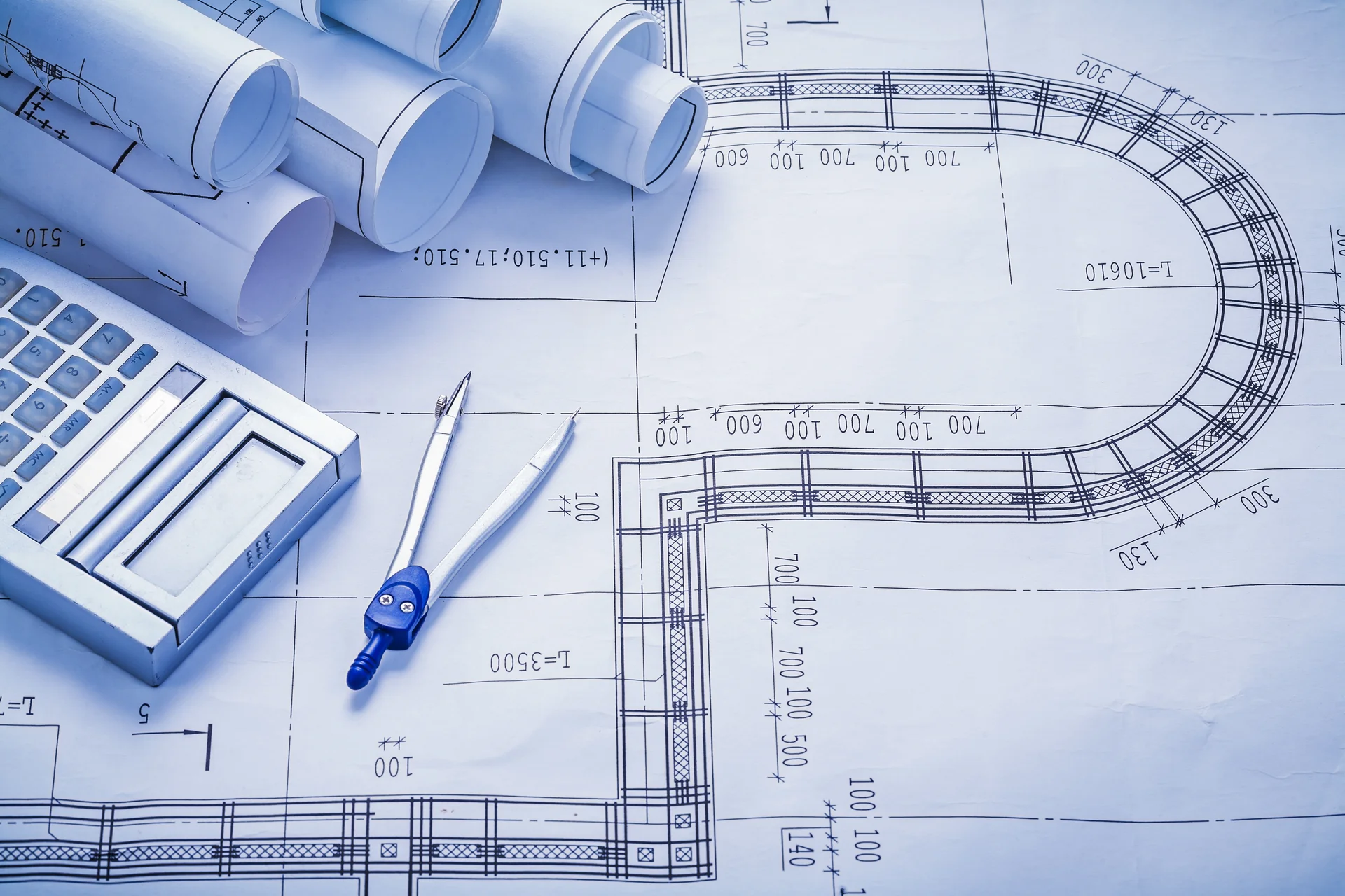
Request the current model sheet together with the machine layout, axis list, tool interface and proposed tooling schedule. For a complex part, request a sequence review that identifies tool clearance and how the blank is gauged at each stage.

Technical drawings with a calculator and drafting compass
Drawing and bend sequence review

Product FAQs

Close-up of a press brake punch aligned with a multi-V lower die.
Tooling reference
Formed sheet-metal channel resting on the front supports of a press brake.
Visual reference · to be replaced

Should we choose by the thickest sheet we process?

Include the thickest part, but state its bend length and frequency. An occasional short thick bracket and a full-length thick panel can demand very different loads and handling arrangements.

Backgauge beam, guide rails and positioning fingers inside a CNC press brake.
Visual reference · to be replaced

Does a higher axis count guarantee better parts?

No. Additional axes help when the geometry uses their movements. Ask which axes move, their travel, and whether positioning is automatic. Tooling, material consistency and setup still influence the finished result.

Segmented press brake tooling held by a clamp with a red release lever.
Visual reference · to be replaced

Can one tool set cover every job?

Rarely. A general set may suit common bends, while tight radii, short flanges, deep returns and cosmetic surfaces can need different profiles or accessories. Check both clearance and tool load.

Cybelec CybTouch control panel mounted on a press brake.
Visual reference · to be replaced

Is ram positioning accuracy the finished bend-angle tolerance?

No. Ram position is one machine measurement. Finished angle also depends on thickness, strength, springback, tooling, deflection and inspection conditions. State the required part tolerance separately.

Request a Quote

Send CHENDA the material grade and thickness, longest bend, finished drawing, inside radius, critical tolerances and normal batch size. Add existing tool details if you want to reuse them, and identify heavy, deep or surface-sensitive parts.

Formed sheet-metal channel resting on the front supports of a press brake.
Start from the finished part