Part identity / Laser marking

Laser Marking Machines for Part Identification, Codes and Engraving

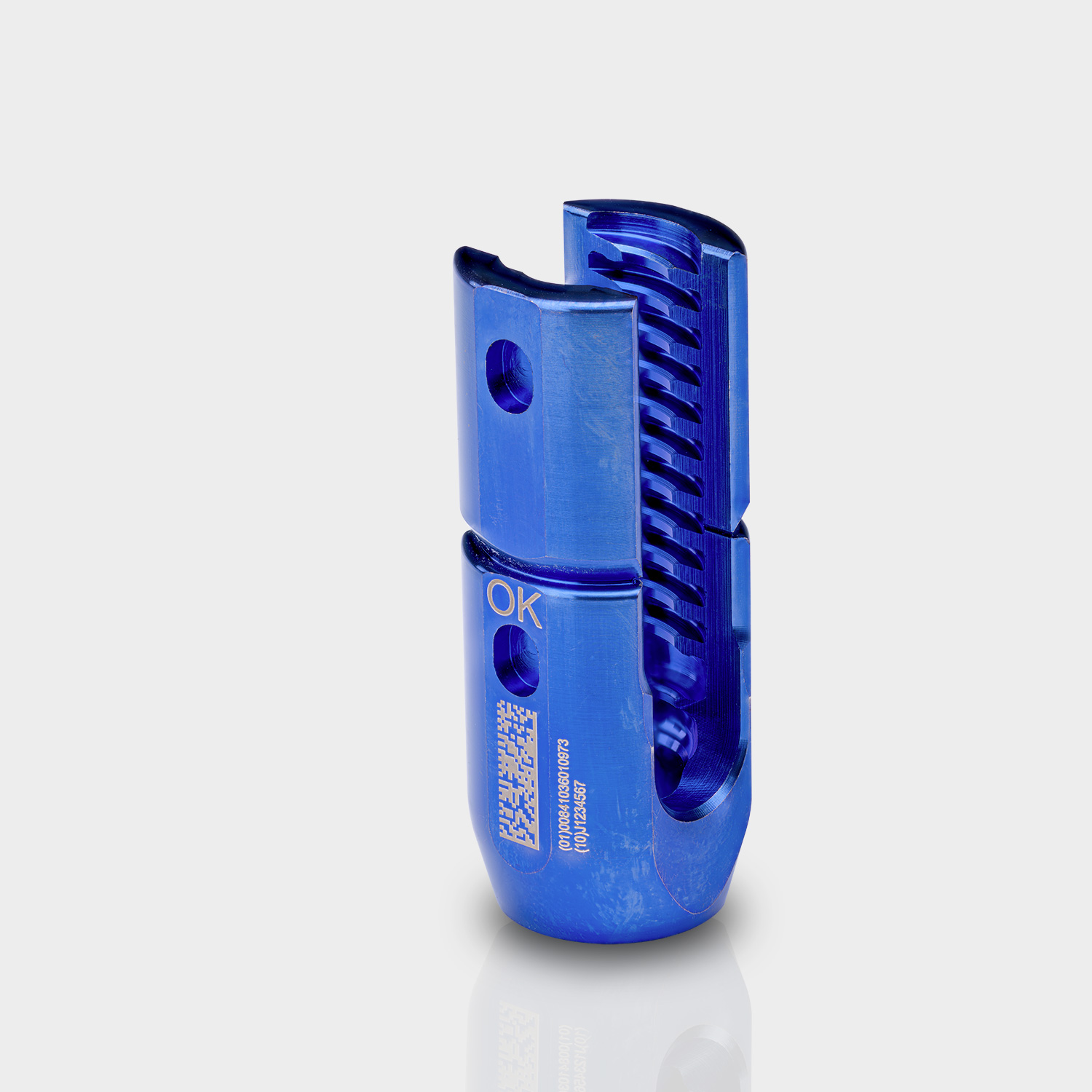
Laser-marked DataMatrix and human-readable identification on a blue-finished aluminum component
Data Matrix on an aluminum component · marking reference · FOBA

Product Overview

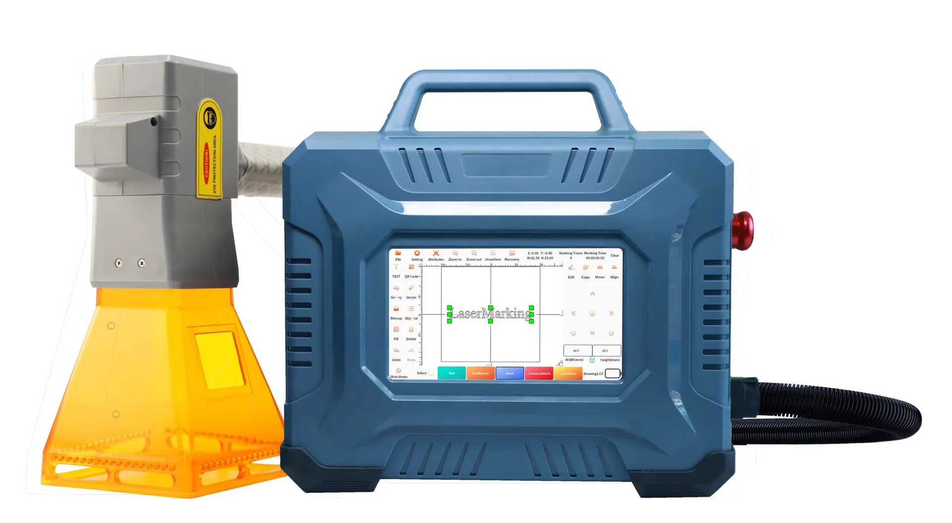
Portable laser marking unit with a touchscreen case and a connected handheld marking head.
Portable marking configuration

Put the right information on the part, in a form that remains useful through production and service. CHENDA fiber laser marking equipment addresses serial numbers, part references, logos and codes on compatible metal surfaces, with compact enclosed and desktop formats represented in the range. Source, optics, workholding and data handling are matched to the mark instead of treating every identification job as the same engraving task.

Choose the system around the mark you need to read. Small text on a machined component, a code on a curved housing and a decorative logo on a visible panel have different requirements for focus, positioning, surface response and data handling.

For metal fabrication, the benefit can be clear part identity through assembly. For a finished component, it can be a durable reference without a separate label. For a batch of nameplates, it can be repeated graphics with changing data. The relevant production measure is a correctly marked, readable part released to the next operation.

Materials & Capabilities

Fiber marking is commonly evaluated for steel, stainless steel, aluminum and other compatible metals. The alloy, heat treatment, plating, anodizing, paint or other surface layer can change the result. A setting that produces good contrast on one batch may not behave the same way on another finish.

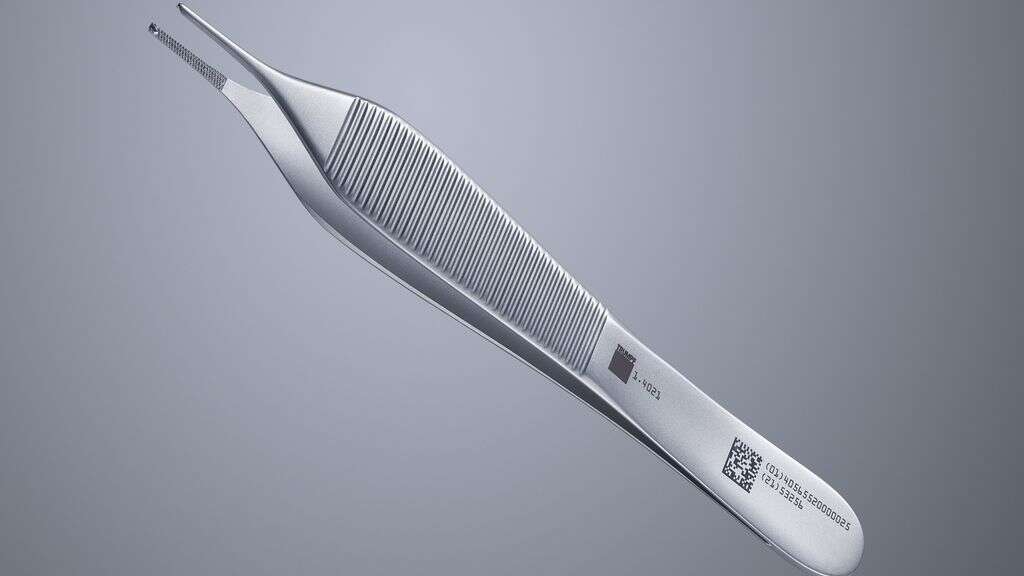
Laser-marked DataMatrix and readable UDI identification on metal tweezers
Identification on a finished metal component · reference · TRUMPF
Material or surface Marking objective Important distinction
Bare metal component Identification, contrast mark or engraving Contrast and material removal are different process outcomes
Anodized aluminum Readable text or graphic Coating color, thickness and sealing influence appearance
Coated or plated metal Controlled surface-layer removal Exposed metal and corrosion protection must be considered
Plastic component Legible identification without unacceptable melting Polymer formulation and additives determine laser response
Cylindrical metal part Code, text or circumferential graphic Surface curvature changes focus and can require rotation

Laser source selection is material-specific. Fiber and MOPA fiber sources are relevant to many metal-marking tasks; UV, green or CO₂ processes may deserve evaluation for other materials. These are process alternatives to discuss, not interchangeable options assumed to be fitted to a CHENDA fiber machine. Suitability and supply configuration must be confirmed for the sample.

Laser-marked DataMatrix and human-readable identification on a blue-finished aluminum component
Contrast on a blue-finished aluminum surface · independent application reference · FOBA

Contrast marking, coating removal or deep engraving?

Contrast marking aims to make information visible with limited change to surface geometry. On suitable metals, an annealing-type mark uses a controlled thermal surface reaction rather than removing a deep cavity. Coating removal reveals a contrasting layer below an anodized, painted or coated face. Engraving removes material to create depth, usually changing cycle time and the appearance of the cavity.

Choose depth only when it serves the part’s life cycle. A component that will be abraded or post-treated may need a different mark from a protected identification plate. Conversely, a sealing face, thin wall or carefully finished surface may not tolerate unnecessary removal. Stainless-steel appearance alone does not establish unchanged corrosion performance after marking; include the relevant downstream exposure in the application assessment.
Features & Engineering

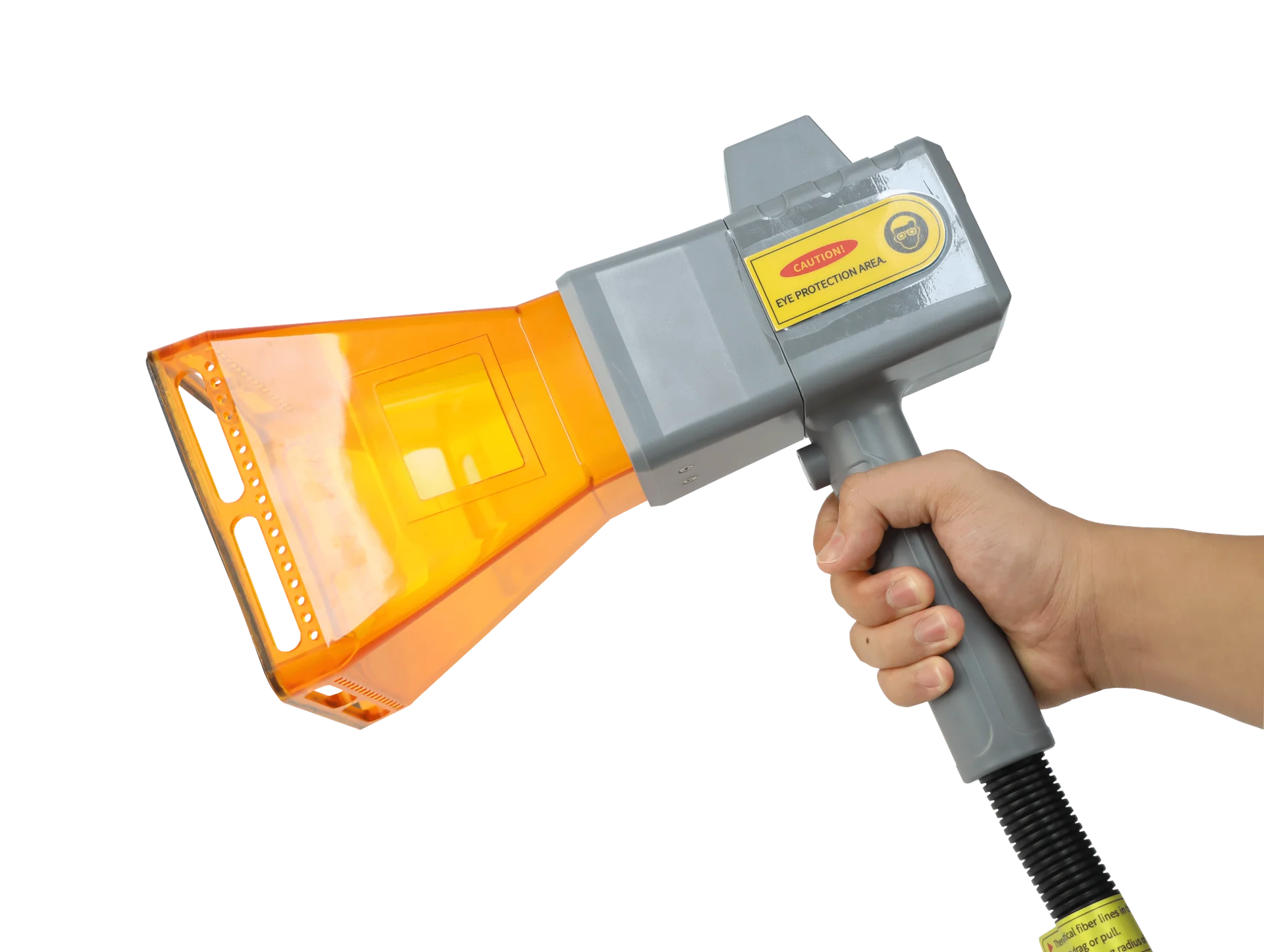
Handheld laser marking head with an orange front shroud and connected cable.
Portable head geometry
Handheld laser marking head with an orange front shroud and connected cable.
Specify the usable field and stand-off

Optics determine the useful marking field

The scan head steers the beam across the lens field. Changing the lens changes the usable area, working distance and spot characteristics. A large field is valuable for large graphics, while fine characters or compact codes may favor a smaller field. Judge the finished mark at the center and relevant edges of the intended work area.

Laser-marked DataMatrix and readable UDI identification on metal tweezers
Fine edges and filled marks on a finished part · TRUMPF

Pulse control and hatch strategy shape the result

On an appropriately configured pulsed source, pulse duration, repetition rate and energy interact with scanning speed and the spacing between adjacent fill lines. Closely spaced hatch lines can increase overlap and cycle time; widely spaced lines can leave a visibly uneven fill. Repeated passes may be useful for depth, but the same number of passes can behave differently if debris, focus or the surface finish changes.

A supported MOPA source adds pulse-duration control as another adjustment. It is useful only when the required material response benefits from that control and the process is validated. It should not be treated as an automatic guarantee of black marks, colored marks or compatibility with every plastic.

Focus and fixtures keep results consistent

A repeatable locating fixture keeps the mark where the drawing requires it. Height variation changes focus; curvature changes both focal position and the apparent code shape. A focus aid, appropriate Z adjustment or a supported rotary arrangement can make setup more repeatable, but each must suit the workpiece envelope.

Laser-marked DataMatrix and human-readable identification on a blue-finished aluminum component
Part geometry determines positioning and focal requirements · FOBA

Data control is part of mark quality

Good contrast does not prevent a wrong serial number. Define the artwork, variable fields, numbering rules and operator permissions alongside the laser settings. A production system may need to load data, check part presence, apply the mark, read it back and record the result. Camera reading and database communication are integration functions to specify separately.

For serialized production, distinguish four events: a job is selected, the marking cycle finishes, the code is decoded, and the decoded value matches the expected record. A completed laser cycle proves only the second event. Where automatic verification is included, the interface should make a mismatch or unreadable code visible before the part moves downstream. The required signals and handling response belong in the line-integration scope.

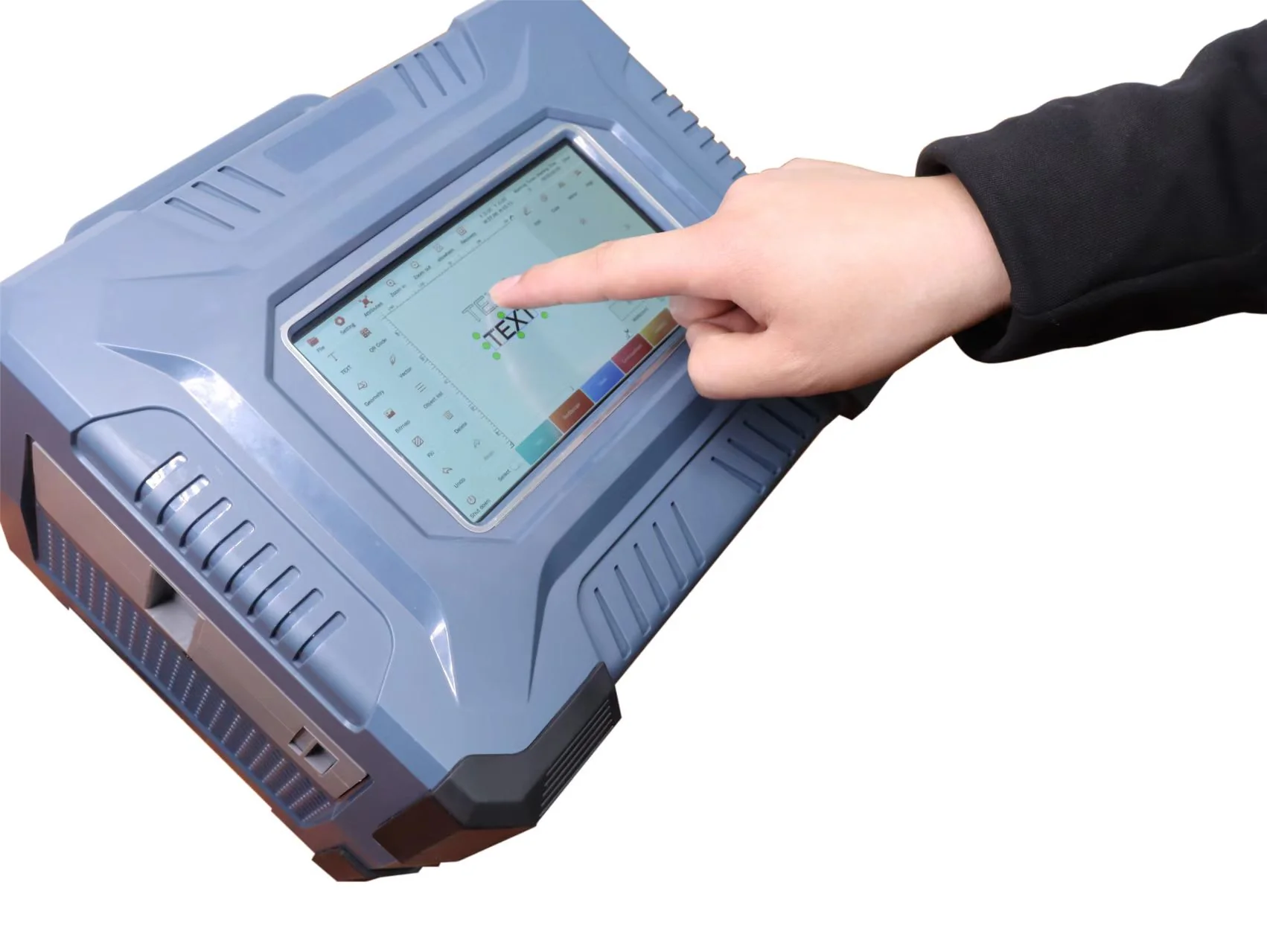
Portable laser marking unit with a touchscreen showing editable text.
Artwork setup on the marking controller
Select jobMarkDecodeMatch record

Technical Specifications

CHENDA’s fiber-marking catalog shows enclosed compact and desktop machine formats with 20, 30, 50 and 100 W source selections. Final source type, optics, work area and workpiece clearance are configuration-dependent; the power choices alone do not determine engraving depth or output.

Portable laser marking unit with a touchscreen case and a connected handheld marking head.
Confirm the complete workstation specification
Selection field Unit or definition How to specify it
Catalog fiber source selections 20 / 30 / 50 / 100 W Confirm the source and usable pulse settings for the required effect
Marking field X × Y, mm State the chosen lens field, not cabinet dimensions
Maximum workpiece envelope L × W × H, mm; mass, kg Include fixtures, loading clearance and rotary accessories
Character and code size mm; module size where applicable Test the actual font, code content and reading distance
Engraving depth mm or µm Agree material, measured depth and allowed surface condition
Complete cycle time s/part Include positioning, data transfer, marking and verification
Positioning requirement mm relative to part datum Separate machine motion from fixture and part variation
Software and data interface File formats, fields and protocol Validate with a representative customer file and data record
Electrical and extraction needs V, phase, Hz; extraction specification Match the selected workstation and processed material

A scanner’s movement speed is not a finished-parts-per-hour rating. Filled areas, repeated passes, code density and depth all change marking time.

Samples & Demonstration

Submit a real part or sample of the production surface with the exact artwork and required mark location. Include the smallest characters, densest code and most difficult curvature. For a code, supply representative data rather than a simplified demonstration string.

Review placement, contrast, edge definition and any surface damage. Check readability using the intended reader, lighting and viewing direction. A successful scan confirms decoding under those conditions; formal code-quality grading requires an agreed verifier and method. If the part will be coated, washed, polished or heated later, evaluate the mark after that operation as well.

Laser-marked DataMatrix and readable UDI identification on metal tweezers
Check the actual text, code and placement on the part · TRUMPF

Why a clear-looking code can still be difficult to read

Laser-marked DataMatrix and human-readable identification on a blue-finished aluminum component
Code detail on a blue aluminum component · process reference · FOBA
Marking condition Potential reading problem What to inspect
Polished or curved surface Reflections reduce the contrast seen by the reader Lighting and viewing angle on the actual part
Fine code with heavy fill Adjacent modules merge or edges become indistinct Module geometry under magnification
Code close to other graphics or an edge Insufficient clear surrounding area Symbol placement and the required clear area
Similar parts at different heights Defocus changes module definition Fixture seating, height variation and focal position

Test more than a visually attractive central-field sample. Include the intended mark position, the normal variation in part finish and the loading arrangement. A retained sample with its exact template and material record makes later troubleshooting much more useful.

Configuration & Options

An enclosed workstation can suit small parts loaded into a controlled marking space. A desktop arrangement can provide convenient access, while open processing requires an appropriate guarded installation. A compact portable head may help reach large parts, subject to stand-off, positioning and the operating-area design.

Configuration discussions can cover lens selection, workholding, Z adjustment, rotary marking, extraction and material-specific parameter control. For a production line, identify the trigger, conveyor speed variation, encoder requirement where relevant, communication signals and reject or stop logic. A rotary accessory for stationary marking is a different project from marking parts moving on a conveyor.

Portable laser marking unit with a touchscreen case and a connected handheld marking head.
Portable head and controller · one configuration reference

Applications & Workflow

Laser-marked DataMatrix and readable UDI identification on metal tweezers
A readable part identity must survive the production route · TRUMPF

For fabricated parts, identification can be added after cutting or after finishing. Early marking helps sorting and assembly, but later grinding, bending or coating may obscure it. Final marking protects appearance and traceability only if part identity has been retained through the preceding operations.

For machined components, reference the mark to a stable datum and keep it away from sealing faces or other functional surfaces unless the drawing permits it. For nameplates, control blank orientation and artwork revision. The typical route is locate the part, select or receive the correct data, verify the template, mark, inspect and release. Batch and serial-number logic should prevent accidental reuse when a cycle is interrupted.

A nest of small metal nameplates and a single large housing illustrate different production priorities. The nameplate nest needs stable pitch, consistent focus and correct data assignment for each position. The housing needs accessible datums, sufficient head clearance and a repeatable marking location. Increasing laser power cannot correct either a misplaced nest or an unstable housing fixture; the workholding and data sequence are the decisive parts of the configuration.

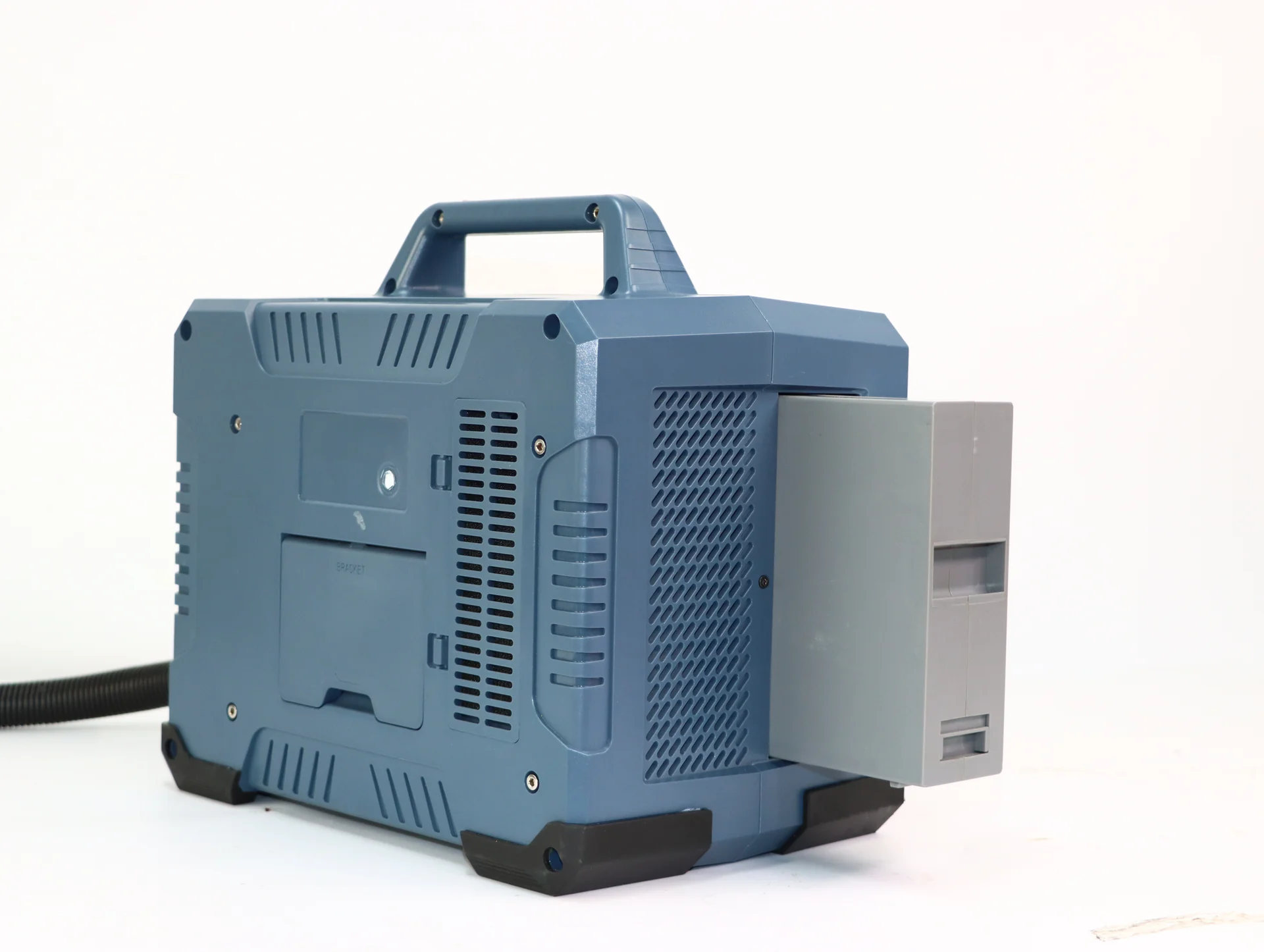
Rear view of a portable laser marking unit with a carrying handle and ventilation grilles.
Plan the equipment position, access and cable routing

Installation & Support

Plan a stable workstation, suitable extraction, electrical supply and access controls for the selected laser configuration. Operator training should include focus setup, lens care, fixture checks, approved recipes and handling of variable data. Back up templates and validated settings before changing software or a control computer.

For troubleshooting, provide the source and lens details, material finish, file and a photograph showing the defect. A faint mark caused by focus or material changes needs a different response from a data or software problem.

Technical Resources

Ask for a source-and-lens datasheet, workstation dimensions, supported software formats and a list of proposed accessories. Where traceability is required, request the variable-data and verification workflow with your sample record. Trial images should be accompanied by the material and process conditions.

Portable laser marking unit with a touchscreen showing editable text.
Check files, fields and supported interfaces

Product FAQs

Handheld laser marking head with an orange front shroud and connected cable.
Laser-marked DataMatrix and readable UDI identification on metal tweezers
Material response reference · TRUMPF

Can the same machine mark every metal and plastic?

No. Material absorption and surface chemistry vary. Confirm the exact alloy or polymer, coating and required effect before choosing the source.

Laser-marked DataMatrix and human-readable identification on a blue-finished aluminum component
Contrast reference · FOBA

Does higher power produce a darker mark?

Not necessarily. Contrast depends on the surface interaction, pulse settings, focus, speed and hatch pattern. More power can remove a layer or change a surface beyond the intended result.

Laser-marked DataMatrix and readable UDI identification on metal tweezers
Code geometry reference · TRUMPF

Can a QR code or Data Matrix fit into a smaller space?

The data content, code structure and module size limit how small it can be while remaining readable. Test the intended code on the actual surface with the production reader.

Laser-marked DataMatrix and human-readable identification on a blue-finished aluminum component
Curved component reference · FOBA

Do round parts always require a rotary axis?

Small marks may fit within a usable focal region on a curved surface. Larger circumferential marks often need controlled rotation or another suitable optical arrangement. The decision depends on diameter and mark width.

Portable laser marking unit with a touchscreen showing editable text.

Can we import our current artwork?

Send the source file for a software compatibility check. Confirm scale, outlines, fonts, fills and variable fields after import; a visually similar preview can still contain different paths or missing text.

Request a Quote

Send the material and finish, part dimensions, mark location, artwork, smallest text or code, required depth or contrast, production volume and the next processing step. Include whether data changes on every part and whether marking will be manual, rotary or integrated into a line.

Laser-marked DataMatrix and human-readable identification on a blue-finished aluminum component
Specify the mark on the actual material and finish · FOBA