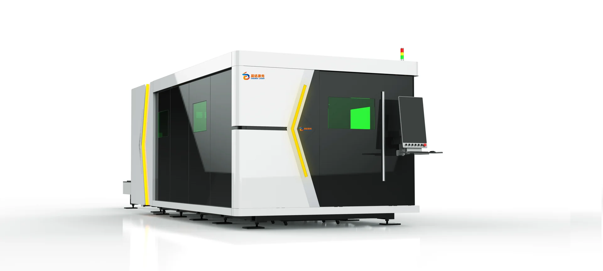
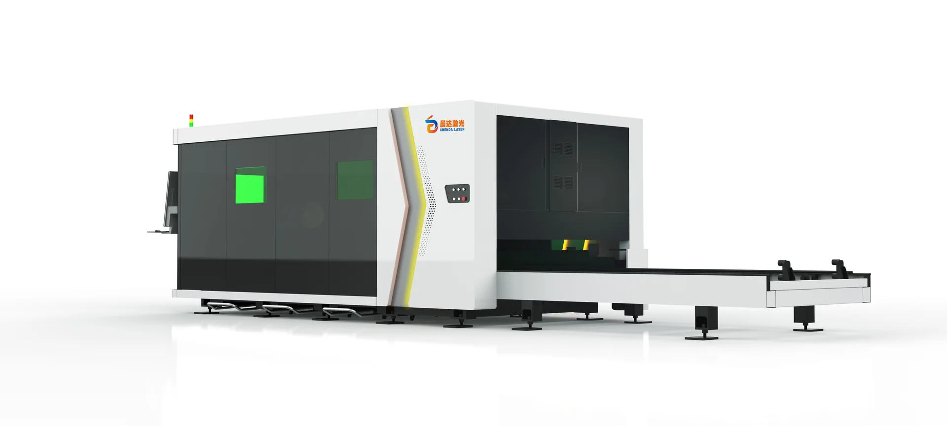
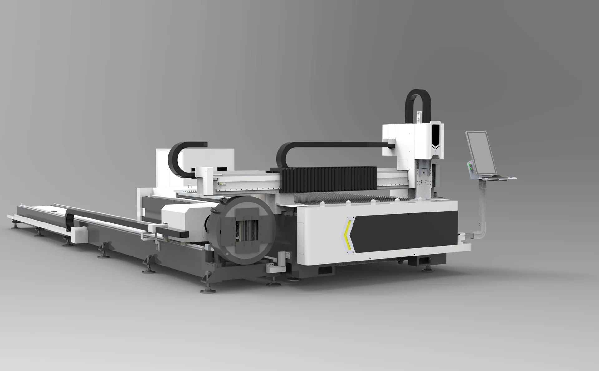
Build your cutting process around the metal you buy and the parts you deliver. CHENDA’s laser-cutting range covers flat sheet, tube, combined sheet-and-tube work and structural profiles. Each route uses a different approach to supporting material, moving the cutting head and removing finished parts.
For a cabinet maker, the priority may be clean blanks that bend consistently. A furniture producer may need accurate tube intersections and repeatable frame fit-up. A steel fabricator may need holes and connection details on long, heavy sections. Start with that production requirement, then select the machine format and laser power.
Fiber laser cutting is a metal-processing route for carbon steel, stainless steel and suitable aluminum alloys, with other metals reviewed against the selected source and cutting system. Material grade, surface coating and thickness affect piercing, edge condition and the useful production speed.
Connection holes, end preparation, notches and suitable bevel features
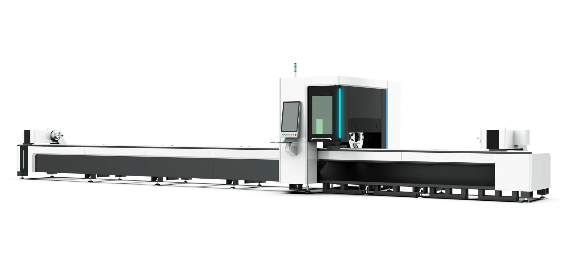
A flat-bed laser does not become a tube machine through software alone. Tube rotation and support, or access to a profile’s web and flanges, require the corresponding mechanical arrangement. A laser program can describe the contour, but the machine must still reach it while the stock remains stable.
Cutting capacity has three different meanings
Severance capacity describes whether the process can separate a material. Production capacity describes whether it can do so repeatedly at an acceptable edge quality and rate. Feature capacity describes whether the particular hole, corner, narrow web or bevel can be made to the drawing. A machine may separate a thick plate while a small hole in that same plate still requires another operation. Selecting against all three prevents a maximum-thickness figure from overshadowing the part that earns revenue.
Features & Engineering
A coordinated machine, from beam delivery to part removal
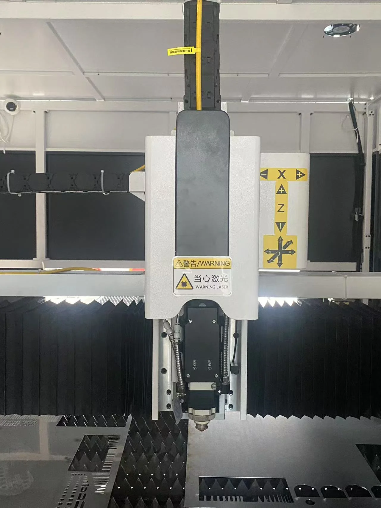
The fiber laser source supplies energy; the cutting head concentrates it and places the focus relative to the material. The motion system carries that interaction around the contour, while assist gas removes molten material. Cooling, gas control and extraction allow these functions to operate as a process. Increasing source output without matching the head, thermal management and gas supply does not establish a higher useful production rate.
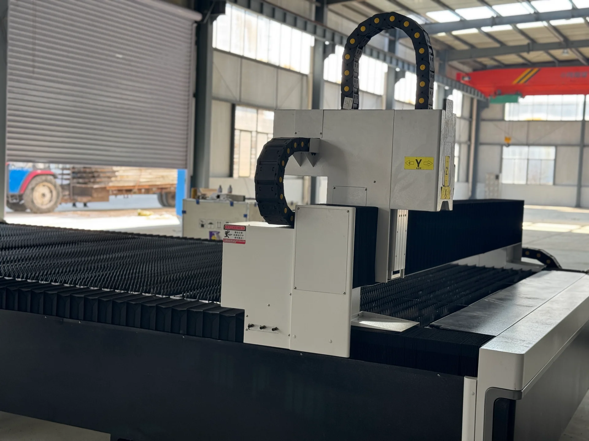
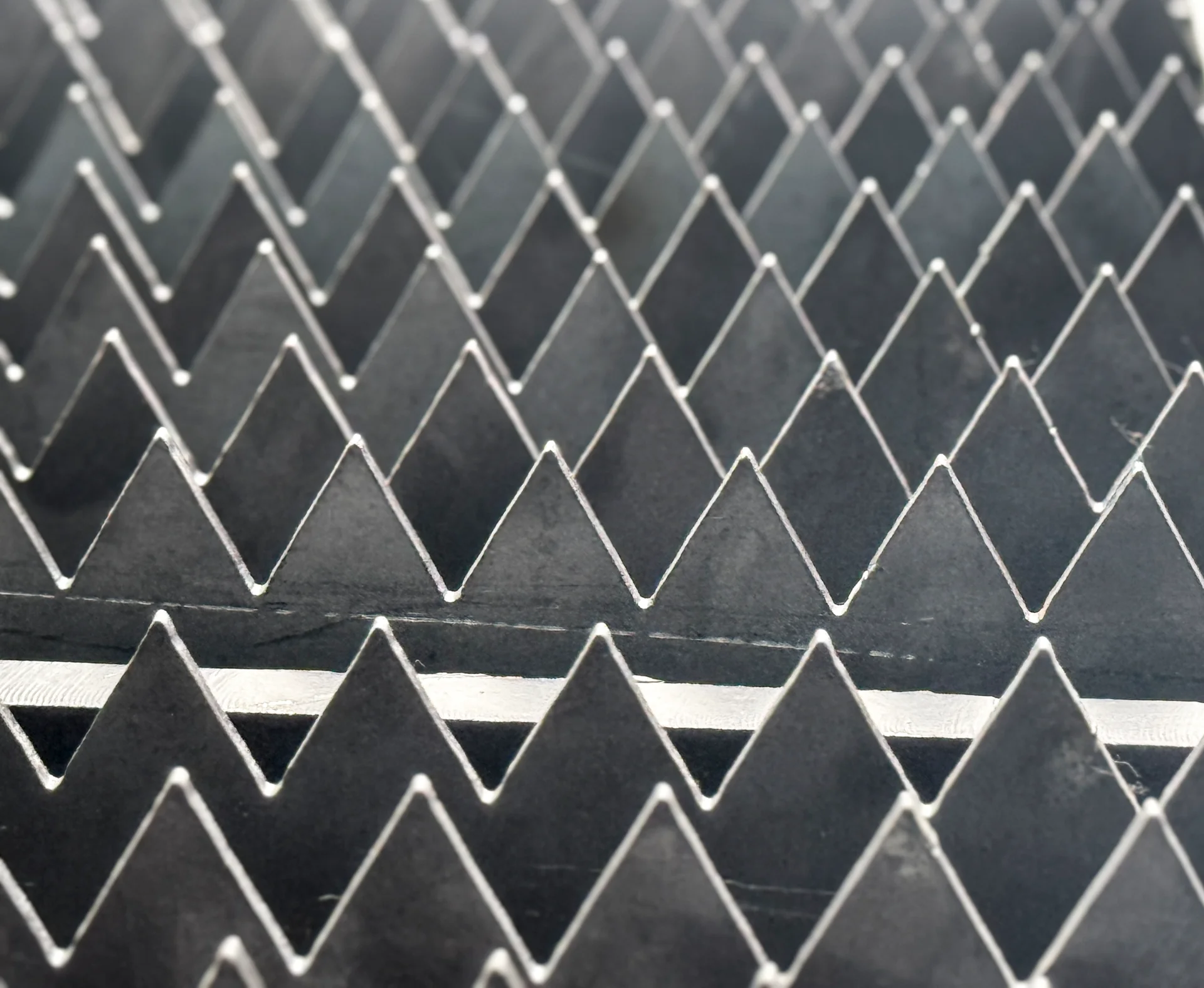
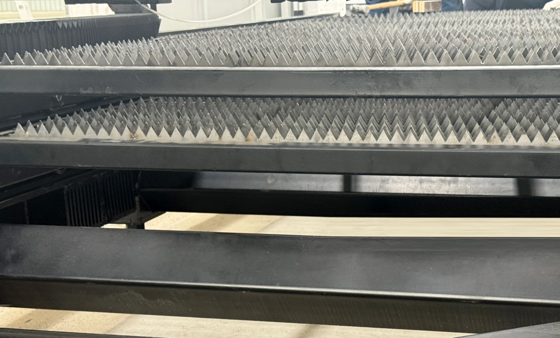
For sheet, the stock rests on slats while the head moves over the nest. For tube, axial feed and chuck rotation cooperate, and supports control the free span. A profile machine adds the access needed around webs and flanges. Each layout solves a different workholding problem, which is why physical fit comes before a comparison of speed figures.
Focus, height and gas perform different jobs
Focus position controls where beam energy is concentrated through the material. Height control maintains the nozzle’s distance from the surface. Gas pressure and flow determine how the process clears the kerf. These are related settings, but they are not interchangeable: raising pressure does not correct a damaged nozzle or an incorrect focus.
Oxygen-assisted cutting introduces an oxidized edge; nitrogen can be selected where avoiding that oxide is important. Air cutting has its own edge and operating-cost tradeoff. The useful comparison follows the part through welding or coating, including any edge treatment it still needs.
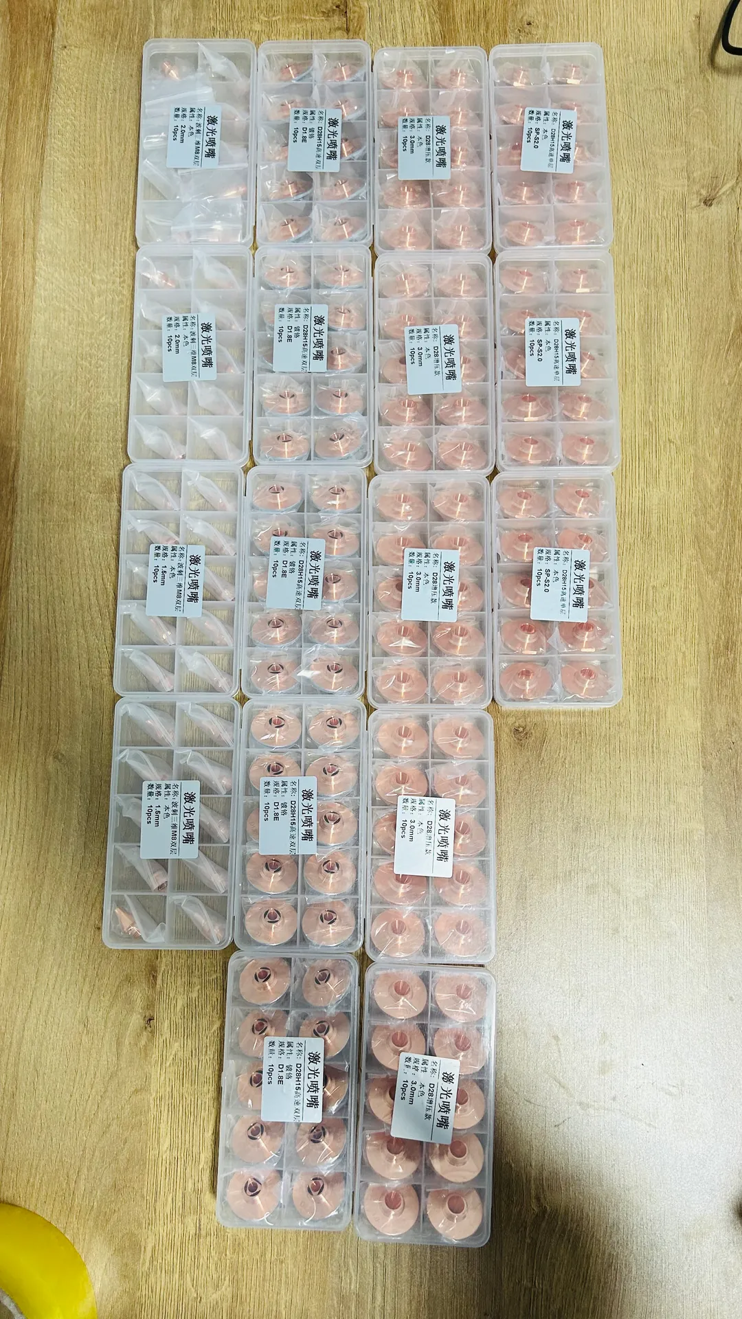
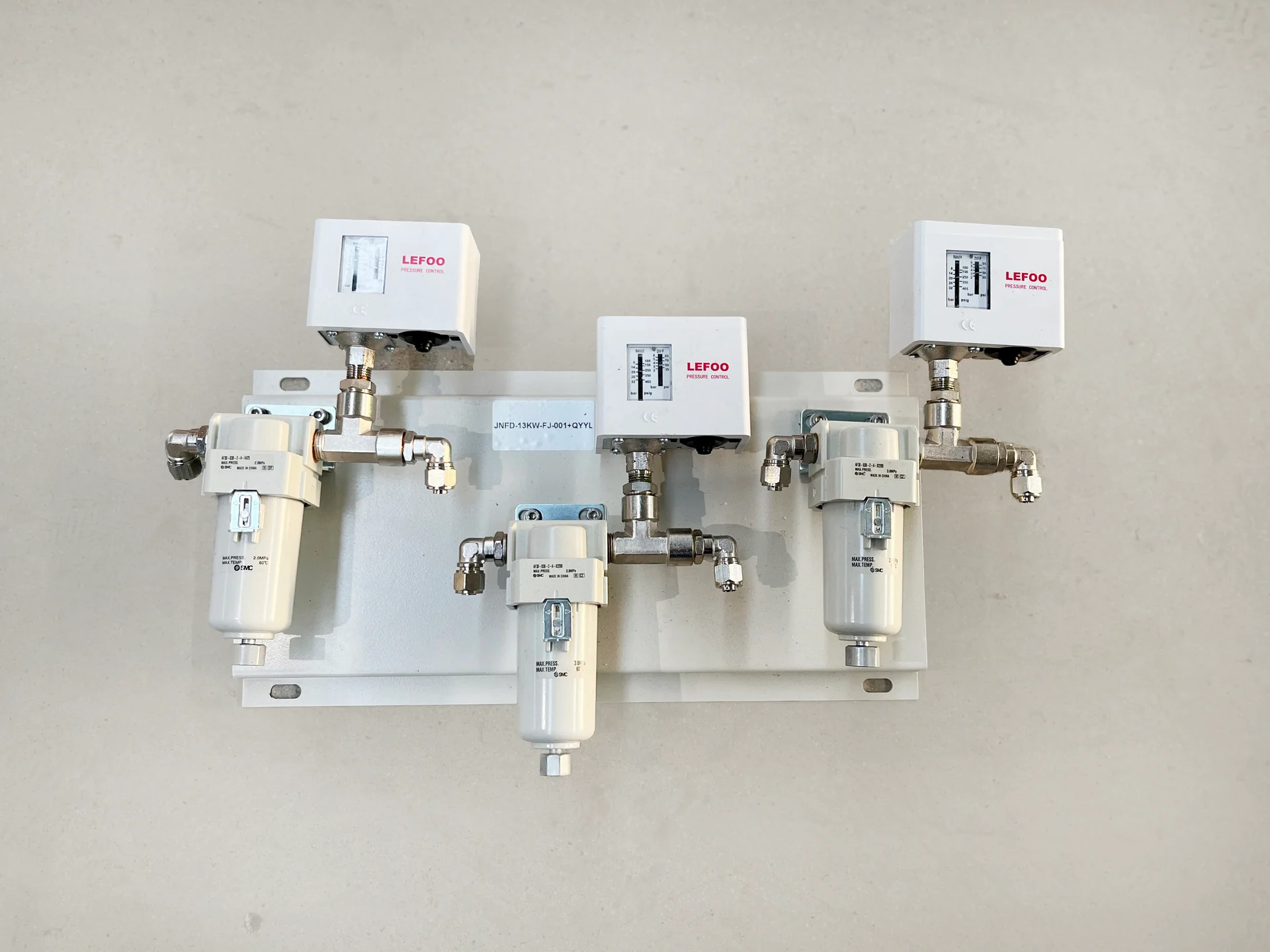
Nozzle selectionGas delivery components
Stability is built into the complete operating cycle
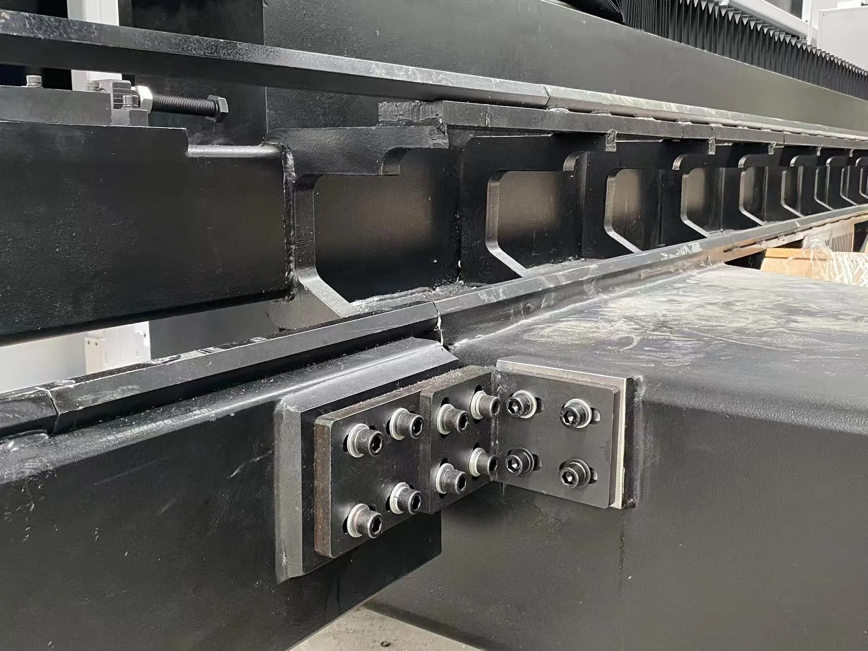
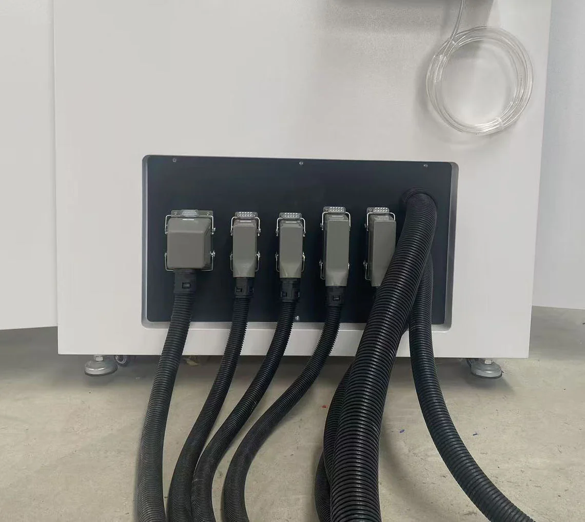
Bed stiffness, rail support, lubrication and protection from accumulated cutting heat contribute to consistent motion. Clean electrical integration and meaningful equipment-state alarms help operators distinguish a gas or cooling interruption from a cutting-parameter problem. These are practical configuration details: their benefit is fewer unexplained interruptions and a clearer route to diagnosis, rather than a decorative list of component brands.
Overlap handling where the product mix allows it
Exchange tables overlap sheet handling with cutting. Tube feeders address repetitive stock loading. A structural-profile line reduces separate positioning for successive preparation operations. Their benefit depends on the complete route. Nesting, part collection and downstream capacity remain part of the equipment decision, particularly when faster cutting creates more parts than the next station can accept.
Technical Specifications
Select the equipment family before comparing its numerical specification. The product pages provide the relevant catalog model references and configuration questions.
Specification to define
Unit or description
Why it changes the proposal
Material and production thickness
Grade and mm
Determines source power, process gas and test conditions
Sheet format
Length × width, mm
Sets working area, nest layout and table loading
Tube geometry
Outside diameter or section dimensions, mm
Sets chuck compatibility, rotational clearance and support
Stock and finished-part length
mm or m
Sets feeding stroke, collection length and required floor space
Material load
kg per item; kg/m for long stock
Affects handling, supports and dynamic performance
Laser output
kW
Must be considered with the required edge and production thickness
Production rate
Accepted parts/hour or batches/shift
Includes piercing, handling, changeovers and sorting
Rapid-traverse speed is not a part cutting speed. A comparison is useful only when material, geometry, gas and outgoing quality remain consistent.
What determines cost per accepted part?
The relevant inputs are stock consumed, cutting and non-cutting time, assist gas, electricity, consumables and any required rework. Scrap reduction may matter more on an expensive tube than a small increase in cutting speed. On a thin-sheet nest, frequent piercing and part sorting may dominate. On a large beam, repeated lifting and locating may be the expensive steps.
The following comparison keeps the machine discussion tied to the product:
Production pattern
Likely limiting task
Equipment feature with a direct connection to it
Thin panels with many ventilation slots
Repeated pierces and short movements
Suitable motion, process control and supported path strategies
Tubular frames with several holes per face
Rotation, locating and collecting finished members
Section-specific chucking, support and tube programming
Long structural members with connection details
Handling and repeated positioning
Accessible profile processing with a consistent datum
Mixed sheet and tube batches
Queueing and changeovers
Combined or dedicated machines selected from the workload split
Samples & Demonstration
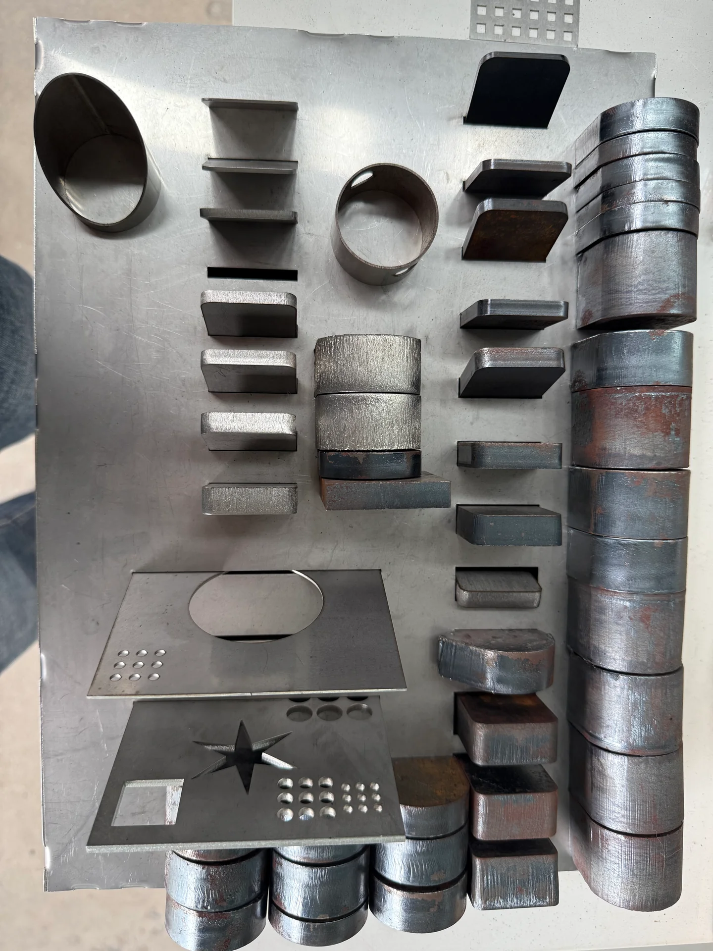
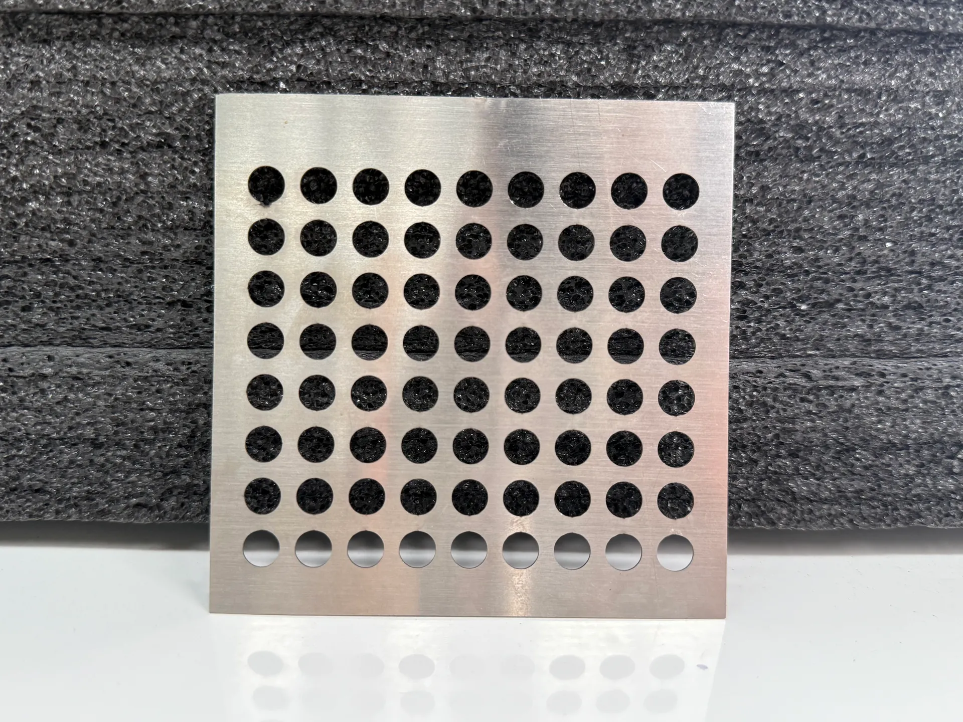
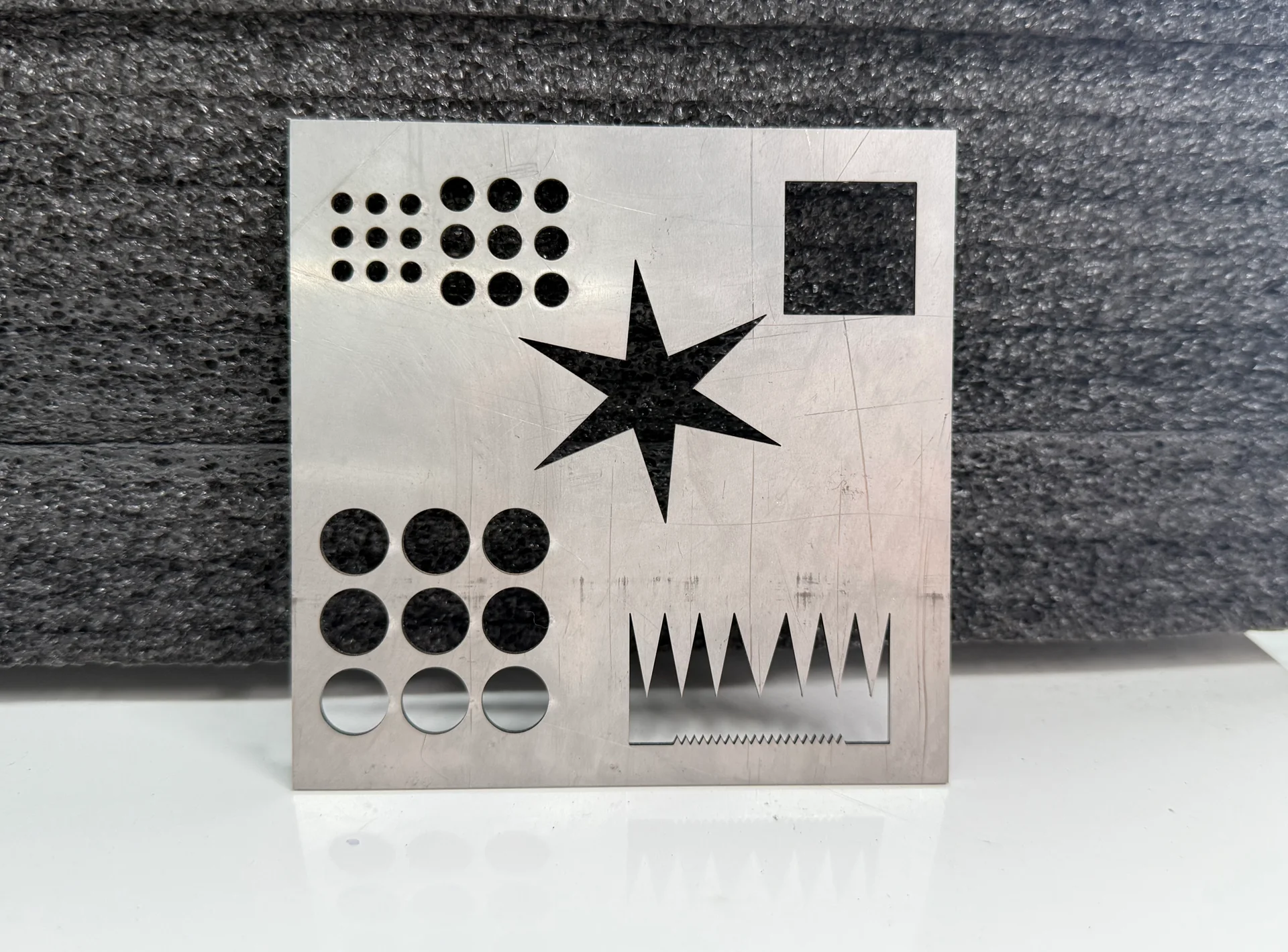
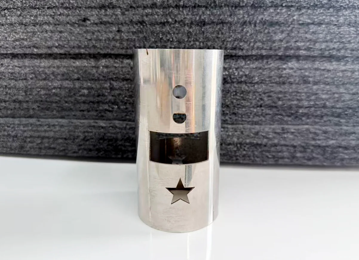
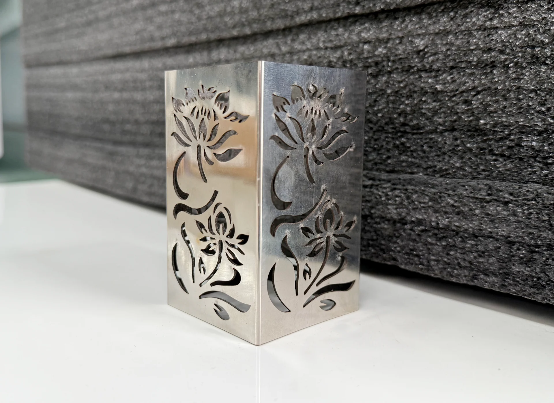
Choose a sample that represents where your current process loses time. For sheet, include dense holes, internal corners and narrow webs. For tube, include holes on more than one face and the actual joint between mating parts. For structural sections, include a flange or web feature near a connection detail.
A meaningful demonstration follows the complete part: load, locate, pierce, cut, remove and inspect. The underside of a sheet edge or the inside of a tube opening can reveal dross or spatter hidden in a front-view photograph. Inspect at least one feature where the process changes direction, reaches a corner or approaches a support-related restriction.
A useful acceptance record separates the finished result from the machine’s motion specification. It connects the drawing revision, material, configuration and measurement to the tested part. This makes an edge-quality or dimensional result interpretable when production later changes to another material batch. Review CHENDA’s quality-control approach for how that record relates to the ordered equipment.
CHENDA’s catalog spans open and enclosed sheet arrangements, exchange tables, dedicated tube configurations and profile-processing layouts. The following systems turn those layouts into different production solutions:
Configuration system
What it changes in production
Source, cutting head and chiller package
The usable power range, optical interface and cooling requirement
Control and programming software
Geometry preparation, process layers, cutting sequence and operator interaction
Regulated assist-gas circuits
Gas selection and repeatable delivery for each material process
Table or chuck arrangement
How stock is held, accessed and released
Loading and collection equipment
Repeated handling effort and the space needed around the machine
Bevel or identification functions
Whether the cut part leaves with the required joint preparation or identity
These are configuration choices, not a statement that every machine contains every function. The ordered equipment list connects each selected function to its hardware, software and operating range. This is especially useful when comparing automation packages that use similar names but handle different stock or unloading tasks.
Applications & Workflow
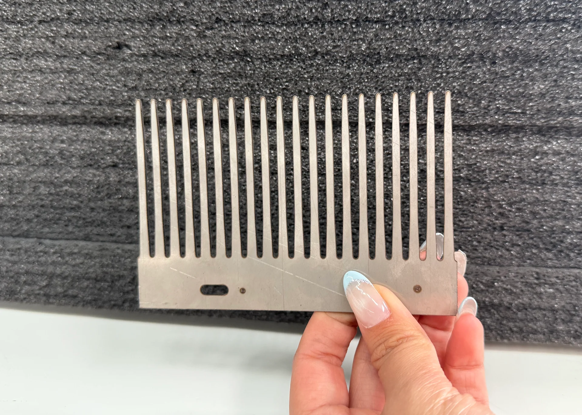
For sheet metal fabrication, the laser creates blanks that move through edge finishing, bending and welding. Consistent holes and locating features help the later assembly.
Cabinet application · visual reference
For metal furniture and cabinets, sheet and tube parts often meet in the same product. Compare combined equipment with separate machines using the workload on each process and the required dispatch date.
Structural application · visual reference
For steel structures, connection geometry and identification must remain tied to the correct member. Plan stock handling, marking, fit-up and welding alongside the cutting line.
Installation & Support
Prepare space for incoming stock, the complete machine envelope, finished parts and maintenance access. A floor plan should also locate the chiller, extraction equipment, assist-gas supply and any compressor package. Long stock requires clear loading paths, not just space equal to the machine’s published dimensions.
Commissioning and training requirements should cover material setup, program transfer, nozzle and protective-window care, gas changes and routine checks for the supplied machine. The handover is more useful when operators finish with a proven starting program for their own part family and a record of the configuration that produced it. See installation and training, production and delivery and spare-parts support for the connected service process.
Technical Resources
Request a family-specific catalog, proposed configuration sheet and layout drawing. For a shortlisted machine, ask for a cutting recommendation using your material distribution and a demonstration tied to your drawings.
Should we select laser power before the machine type?
Start with stock geometry and production demand. A higher-power sheet machine cannot replace the chuck travel, tube support or profile access your work requires. Power selection follows the machine’s physical suitability.
Can one machine handle sheet, tube and large beams?
A sheet-and-tube configuration combines specific sheet and tube capacities. Large structural members require a separate review of section size, weight and cutting access. Do not assume every profile fits a tube attachment.
Will laser-cut parts go directly to the next operation?
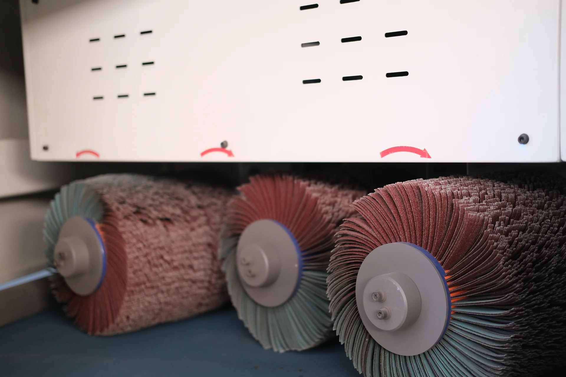
Some can; others need dross removal, edge rounding, oxide removal or precision machining. The drawing, coating system and joint requirements decide which secondary operations remain.
How should we compare two quotations?
Use the same part set and check the complete offered equipment: working range, source, head, software, material handling, utilities and acceptance conditions. Compare accepted output and operating inputs as well as the machine price.
Can we reuse the same cutting settings after changing gas supplier or material grade?
Treat the existing setting as a starting reference. Surface condition, actual thickness and gas delivery can change the result even when the program is unchanged. Evaluate the first parts before committing the batch, particularly when the edge goes directly to coating or a close-fitting joint.
Send representative drawings, material grades, thicknesses, stock sizes and the expected production mix. Include your current handling method and any edge condition that matters before bending, welding or coating. CHENDA will use those inputs to discuss the appropriate cutting family and configuration.