Digital patterns / Physical products

Digital Knife Cutting Machines for Packaging, Textiles and Flexible Materials

CHENDA digital knife cutting table on a white background
CHENDA digital cutting table

Product Overview

Move from a digital pattern to a physical component without making a dedicated cutting die for every design. CHENDA digital knife cutting equipment addresses sample development, changing designs and suitable sheet or roll-material production. A programmed cutting path, matched blade and controlled material support allow the same table to work through different patterns using the tools selected for the application.

The value lies in matching the cutting method to the finished part: a clean foam insert, a carton that folds accurately, an upholstery panel that retains its shape or a printed graphic cut in register. Blade selection, vacuum hold-down, feed behavior and file preparation matter as much as the table size.

This is particularly relevant when a design changes before volume production, several orders share a material, or a prototype must be assembled and revised quickly. The material still needs to be stable under the tool, and the selected process must leave an edge or fold that works in the finished product.

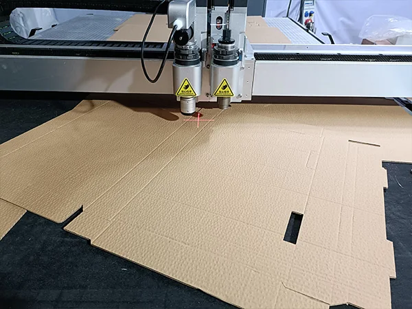
Third-party photograph of digital cutting heads above a corrugated carton blank with cut tabs, slots and fold lines
Cut contours and fold lines on a corrugated blank · application reference · CNC Amor (source publisher; photographer not stated)

Materials & Capabilities

Evaluate the actual material grade, thickness and construction. Two foams of equal thickness can need different blades because density and compression differ. A woven fabric and a stretch upholstery material behave differently under vacuum and tool movement. Laminated board may need different cut and crease settings from uncoated board.

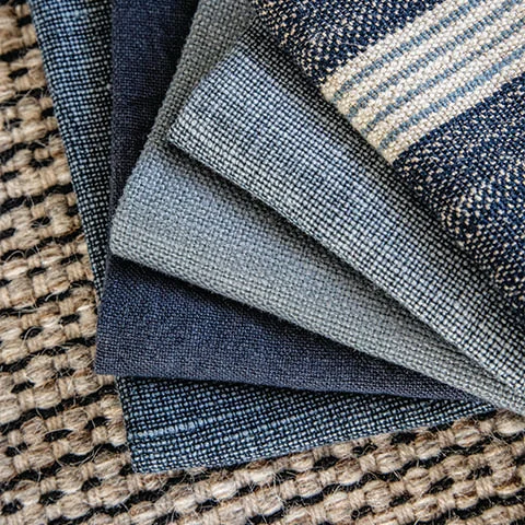
Third-party photograph of overlapping blue and grey upholstery fabric swatches with different woven textures
Woven material samples · material reference · Quintus / Westbury Textiles (source publisher; photographer not stated)
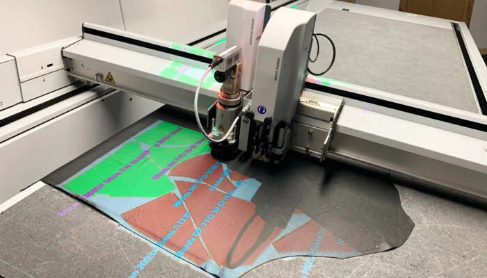
Third-party photograph of a Zünd digital cutting head above leather with colored projected nesting outlines
Leather cutting and projected nesting · process reference · Zünd (source publisher; photographer not stated)
Material direction Work to evaluate Critical trial detail
Paperboard and corrugated board Carton outlines, slots and creases Flute or grain direction, fold quality and printed surface
Suitable foam sheet Inserts, protective shapes and pads Density, compression, edge taper and small internal features
Upholstery and textile material Panels, notches and pattern pieces Stretch, weave, fraying and orientation rules
Leather or synthetic upholstery Shaped pieces and matching sets Surface variation, defects and part orientation
Flexible sign and printed media Contour cutting and supported kiss cutting Registration, liner integrity and feed stability
Suitable gasket or rubber sheet Flat profiles and openings Hardness, reinforcement, thickness and dimensional recovery

These are application directions for material testing. They do not establish a universal material list or a common thickness limit. A knife table should not be assumed to cut metal sheet, every rigid plastic, or a tall stack of textile simply because the material fits beneath the gantry.

Features & Engineering

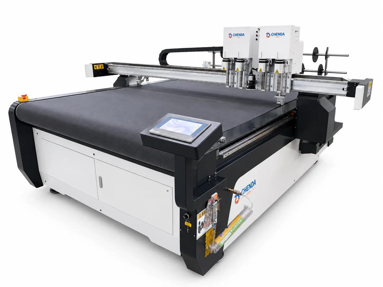
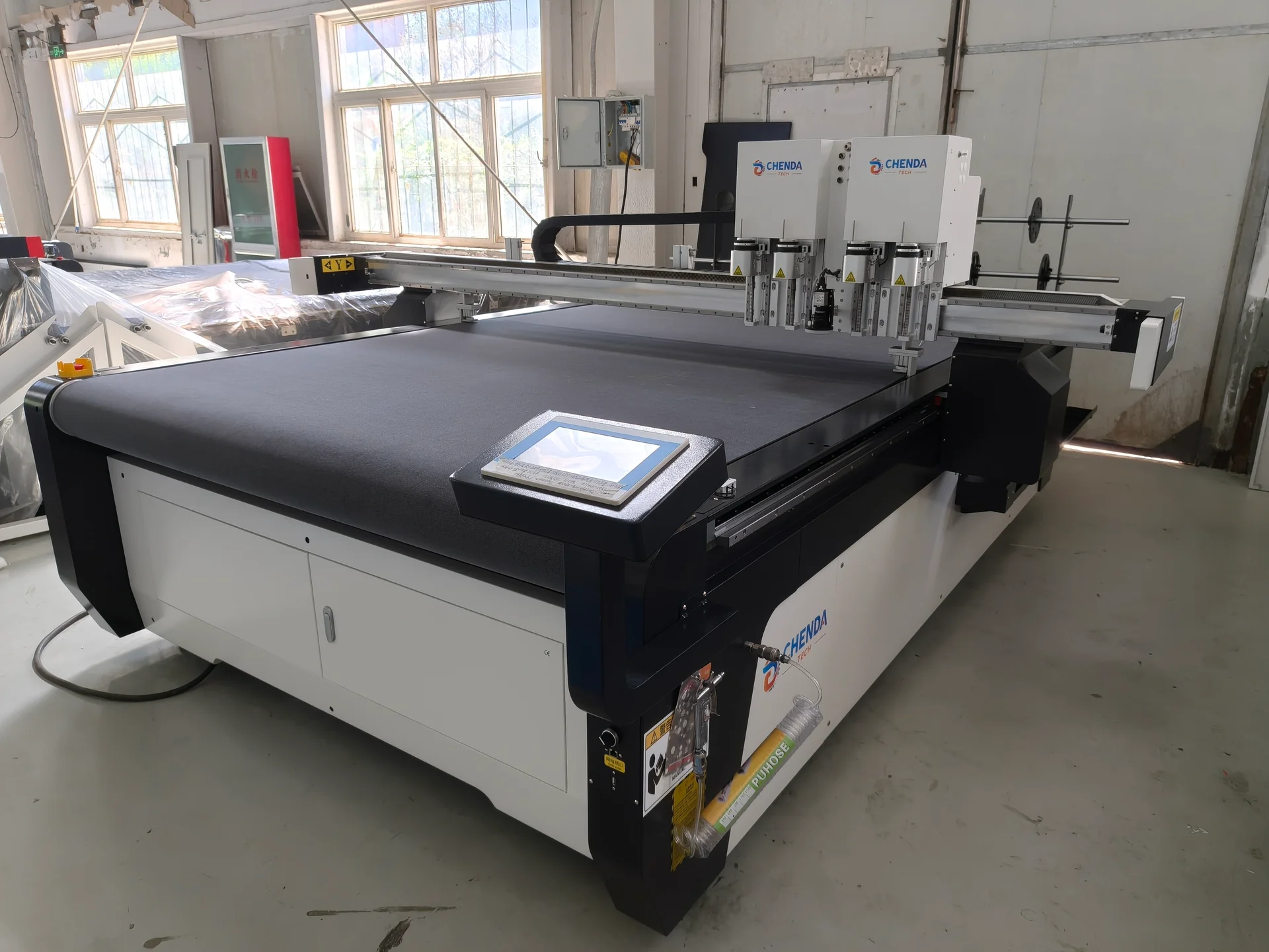
CHENDA digital knife cutting table with twin tool housings and front touchscreen
Table, head and material support
Third-party photograph of a Zünd digital cutting head above leather with colored projected nesting outlines
Tool selection starts with the production material · Zünd (source publisher; photographer not stated)

Select the cutting action

An oscillating blade can help penetrate suitable soft or medium-density materials. A driven rotary tool may suit textiles that tend to drag under a stationary blade. A tangential knife follows controlled orientation around a contour, while a creasing wheel forms fold lines rather than cutting through the board. V-cutting, perforation, punching and marking require their own supported tools and processes.
Blade geometry matters at corners and small features

A blade cuts with an edge that occupies space through the material thickness. Its tip geometry can make the entry and exit behavior different from the line shown on screen. At a tight corner, the blade may need a controlled lift, rotation or path compensation to avoid a torn corner, an uncut bridge or excessive overcut. The useful combination depends on blade shape, material depth and contour size.

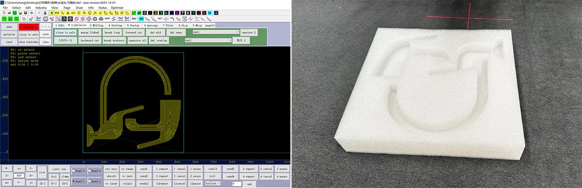
That is why the smallest slot, hole and inside corner should appear in a material trial. A tool that follows a large outside rectangle cleanly may not produce a small foam opening with the same quality. More cutting depth can separate the material while also damaging the underlay or increasing overcut; depth and path compensation need to be considered together.

Third-party side-by-side reference showing CAD cutting geometry and a photographed white foam insert with cut cavities
Drawing beside a cut foam sample · CAD and process-photo reference · slcnccut.com (source publisher; photographer not stated)

Hold the material where the file expects it

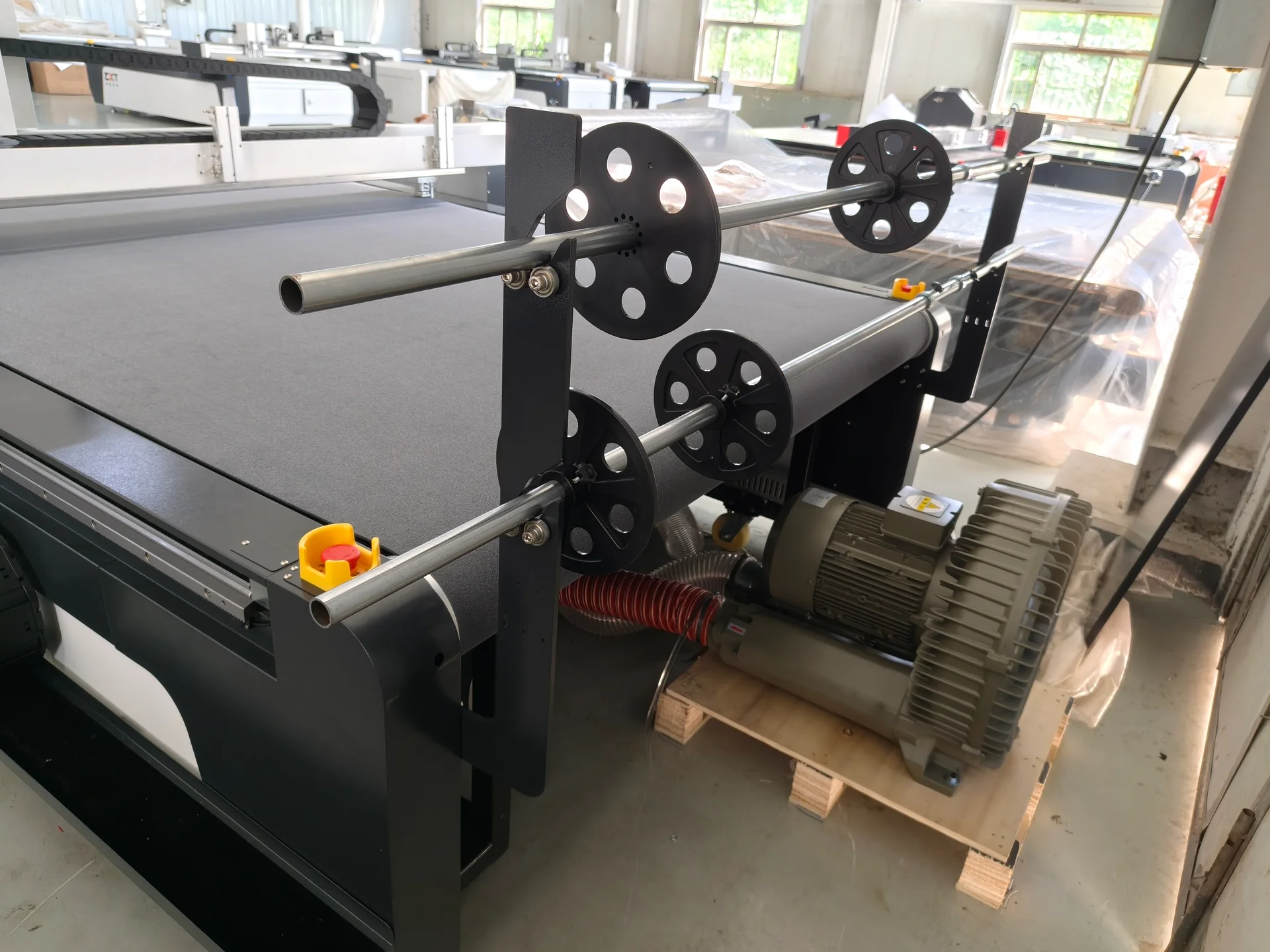
Vacuum hold-down depends on material porosity, the cutting underlay and the area left uncovered. Zoned suction can focus the available hold-down on the working area. Thin or porous material may need an appropriate covering or handling method; simply increasing blade force can cause distortion instead of solving movement.

Hold-down also changes as a nest is cut. Small pieces can become less stable after their surrounding material is separated. Cutting internal features before releasing the outer contour may help appropriate jobs retain support, but the final sequence depends on the material and tool. Collection should avoid disturbing work that has not yet been processed.

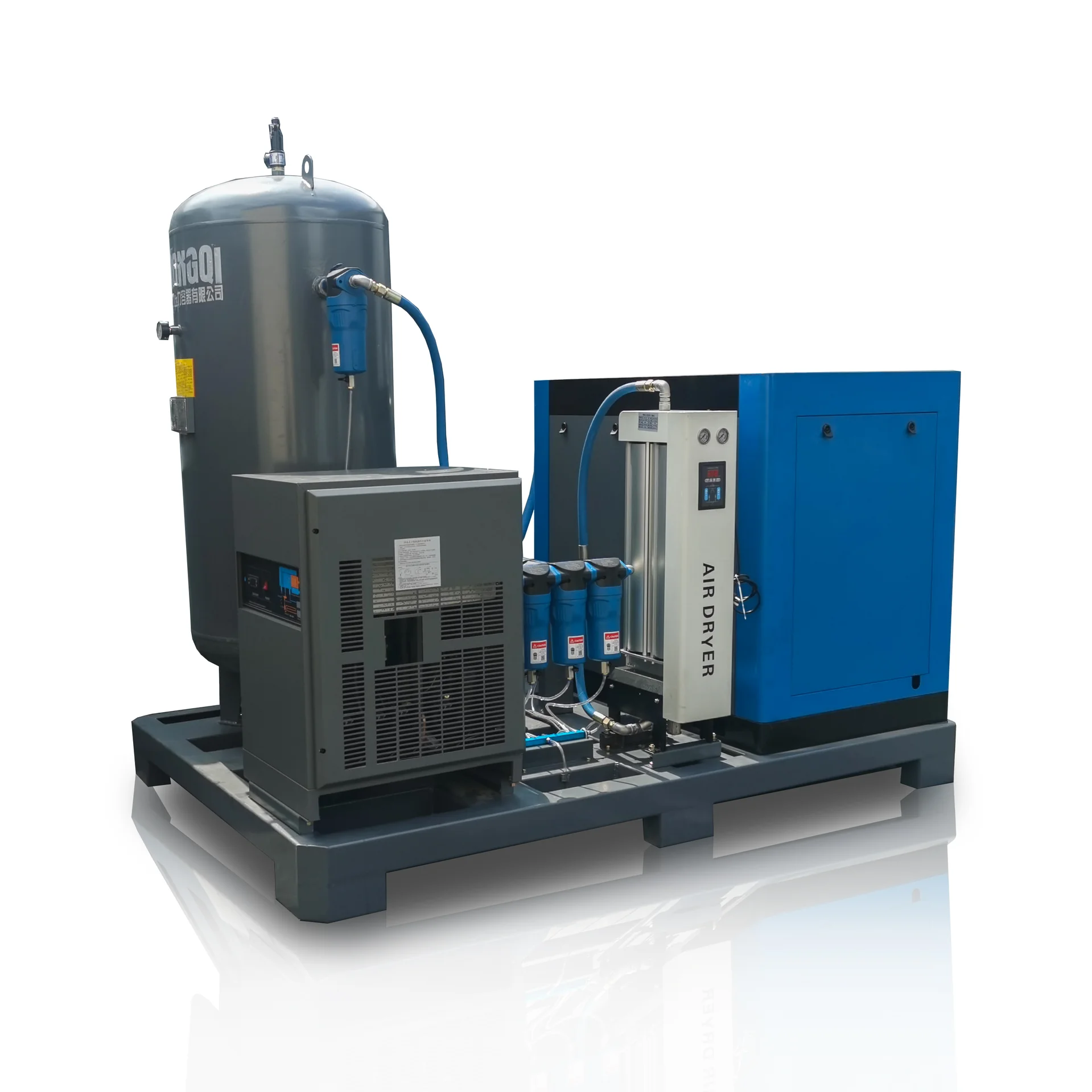
Roll support shafts and an external vacuum blower beside a digital cutting table
Roll support and vacuum blower arrangement

Keep registration through the whole job

For printed work, a supported camera-registration system can relate the cut path to printed reference marks. It must be validated against the expected print distortion and surface contrast. Roll feeding introduces tension and alignment as additional variables. Long parts cut across more than one feed window require a proven registration method between advances.

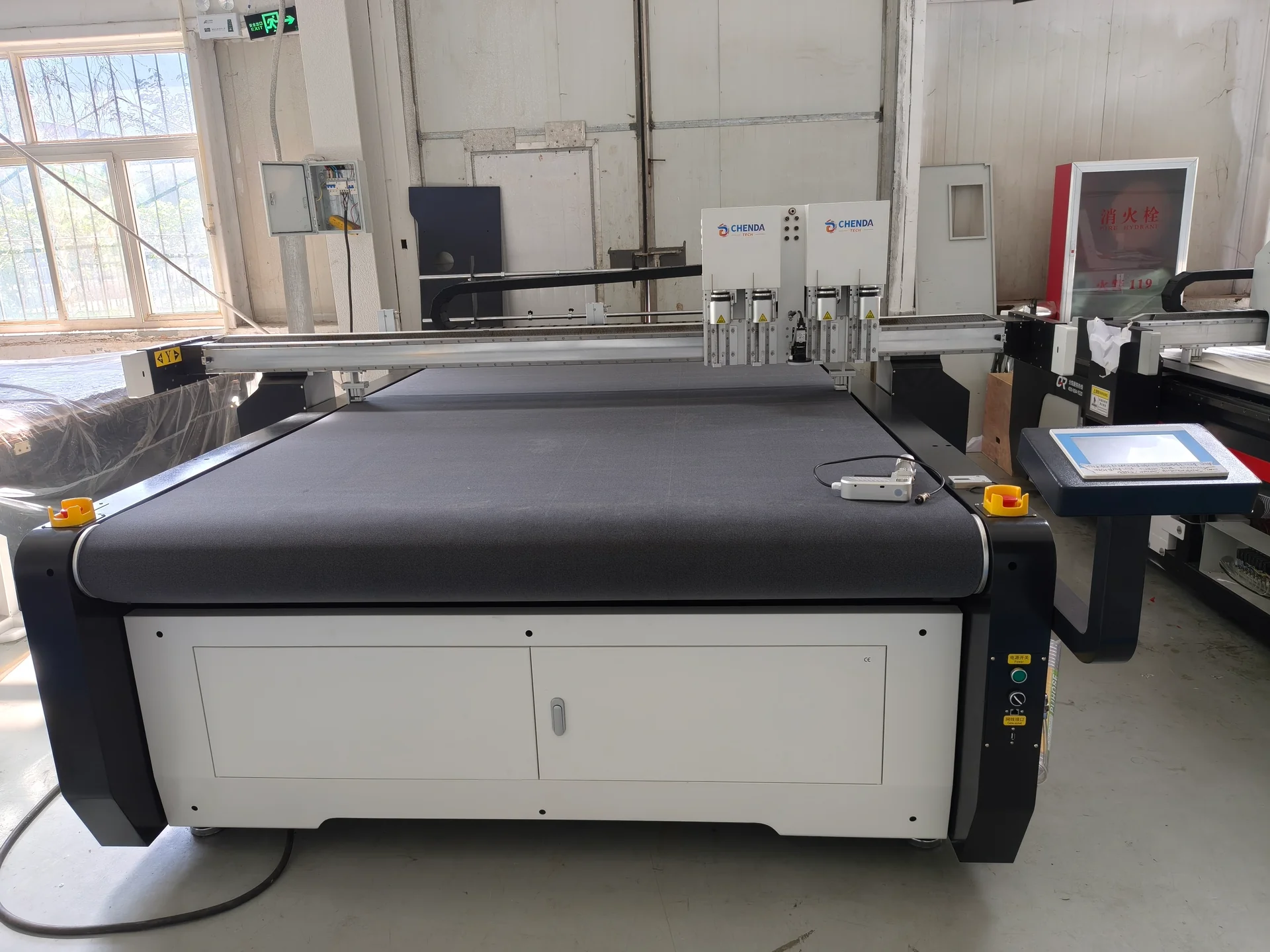
Front view of a CHENDA digital knife cutting table and conveyor bed
Validate registration over the usable table and feed sequence
Third-party photograph of digital cutting heads above a corrugated carton blank with cut tabs, slots and fold lines
Cut and fold features must have distinct manufacturing roles · CNC Amor (source publisher; photographer not stated)

Give each drawing layer a manufacturing role

A cut line, crease line, notch and registration mark may look similar in a design file but require different machine actions. Map them to the intended operations, remove accidental duplicate contours and check units before nesting. A raster image can guide visual placement but is not automatically a usable vector cutting path. File-import compatibility includes this interpretation, not just whether the software opens the file.

For kiss cutting, the tool must separate the required upper layer while retaining the backing. The useful depth window is affected by material and liner variation, table condition and blade setup. A successful through cut does not establish kiss-cut capability on the same stock.

Technical Specifications

The cutting envelope and performance are selected for the material-and-tool combination. Use the following fields to compare the proposed configuration and its trial result.

CHENDA digital knife cutting table on a white background
Specify usable area with the selected tooling
Specification Unit or description Application condition
Effective working area X × Y, mm Usable cutting area with the selected tools and sheet loading
Material thickness mm Maximum usable thickness for each tested material and tool
Layer count Layers; compressed height, mm Validate top-to-bottom consistency; do not infer multilayer capacity
Cutting tools Type, blade and supported process Distinguish through cutting, kiss cutting, creasing and other operations
Cutting speed mm/s Measure on the actual contour, including corners and tool changes
Part accuracy mm relative to the pattern Include material movement, compression and recovery after cutting
Vacuum system kW; zones and control Match leakage, exposed area and material hold-down
Roll handling Width, mm; roll mass, kg Include tension, loading access and collection method
Vision registration Mark type and compensation method Verify with a representative printed sheet or roll
Input data File formats and layer mapping Test cut, crease, notch and print-reference interpretation

Travel speed describes motion; it does not describe output from a detailed nest. Production estimates should include preparation, feeding, cutting, collection and sorting.

Samples & Demonstration

Provide the production material and a file that includes the features most likely to fail. A packaging trial should include short slots, tight corners and fold lines across relevant grain directions. Fold and assemble the sample after cutting. A textile trial should include notches, curves and paired pieces, with measurements taken after the material has relaxed.

For foam, inspect vertical edge quality, small holes and compression recovery. For printed graphics, compare registration at several positions across the sheet. Record the blade, underlay, hold-down arrangement and feed sequence; these can explain a result more usefully than a video of the tool moving quickly.

Third-party photograph of digital cutting heads above a corrugated carton blank with cut tabs, slots and fold lines
Include slots, corners and fold lines in the test file · CNC Amor (source publisher; photographer not stated)
Sample defect What it can indicate Detail to compare in the next trial
Foam opening smaller at its lower face Blade deflection, compression or cut geometry Top and bottom dimensions after recovery
Fabric pieces change shape after removal Tension or stretch during loading Dimensions in a relaxed state and permitted material orientation
Printed outline fits at one corner only Registration or print distortion issue Deviation across the full working area
Carton fold cracks or springs open Crease process mismatched to board and direction Fold behavior after assembly, including coated faces
Liner cut through during kiss cutting Depth window or stock variation Backing integrity across the sheet, not just at one position

The observations are starting points for analysis, not automatic diagnoses. They help select the tool, handling and control functions around a finished product that can actually be used.

Configuration & Options

Begin with the table format, tool heads, cutting surface, hold-down system and compatible control software. Confirm the tools needed for the first production jobs before adding functions that do not serve a defined material.

Options to discuss include a conveyor table, roll support and feed control, camera registration, suitable creasing tools, tool-changing arrangements, nesting software and part-identification marking. A milling or routing function, where proposed, requires separate confirmation of the spindle, material compatibility and dust handling; it is not implied by a knife-cutting specification.

Include blades, cutting mats or underlay, and other startup consumables in the scope where agreed. Define software licenses, supplied modules, accepted file versions and the computer arrangement instead of assuming all design software is included.

Roll support shafts and an external vacuum blower beside a digital cutting table
Feed support and hold-down belong in the configuration

Applications & Workflow

Third-party photograph of digital cutting heads above a corrugated carton blank with cut tabs, slots and fold lines
A packaging blank is evaluated after cutting and assembly · CNC Amor (source publisher; photographer not stated)

For packaging, import the dieline, separate cut and crease layers, respect board direction, nest, process and assemble a trial carton. Use the assembled fit to review tabs, slots and fold allowances before repeating the job.

For upholstery, retain grain or stretch direction and matched-piece requirements during nesting. A nest with less waste may still be wrong if parts rotate against the fabric’s permitted orientation. For print finishing, establish registration marks in the print workflow and confirm that cut files remain tied to the correct artwork revision.

Collection is part of production planning. Small cutouts, closely nested pieces and mixed orders require space and identification so the time saved in cutting is not lost in sorting.

Packaging inserts and upholstery panels use different nesting rules

Third-party photograph of overlapping blue and grey upholstery fabric swatches with different woven textures
Material direction is a product requirement · Quintus / Westbury Textiles (source publisher; photographer not stated)

A foam insert may favor compact nesting, clean cavities and sufficient support around narrow walls. An upholstery set may require every piece to follow a common grain or stretch direction, with paired parts kept together for sewing. In the second case, rotating a piece to save area can damage the value of the whole set. Good nesting therefore optimizes material use within the product’s rules rather than treating every contour as freely rotatable.

For corrugated packaging, crease direction and cut sequence belong to the same job recipe. Folding a prototype exposes tab fit, panel interference and springback that a flat sample cannot show. Design revision then returns to the digital file, making short development loops one of the practical reasons to choose digital cutting.

Third-party side-by-side reference showing CAD cutting geometry and a photographed white foam insert with cut cavities
Cavities and supporting walls in a foam insert · drawing and sample reference · slcnccut.com (source publisher; photographer not stated)

Installation & Support

Plan access around the table, sheet or roll-loading space, vacuum-pump ventilation and room to collect finished pieces. Confirm electrical supply and any compressed air required by the selected tools. The table must be installed and set up according to its leveling and support requirements.

Training should cover file scale, process layers, blade depth, tool calibration, hold-down, safe blade replacement and a first-piece check. Routine service includes the cutting surface, blades, vacuum path and any feed or vision components in the configuration.

Retain the production file together with tool identity, material description and the accepted setup. Replacing a blade with another geometry or changing the underlay can require calibration even when the part file is unchanged. The handover should make these setup dependencies understandable to the operator.

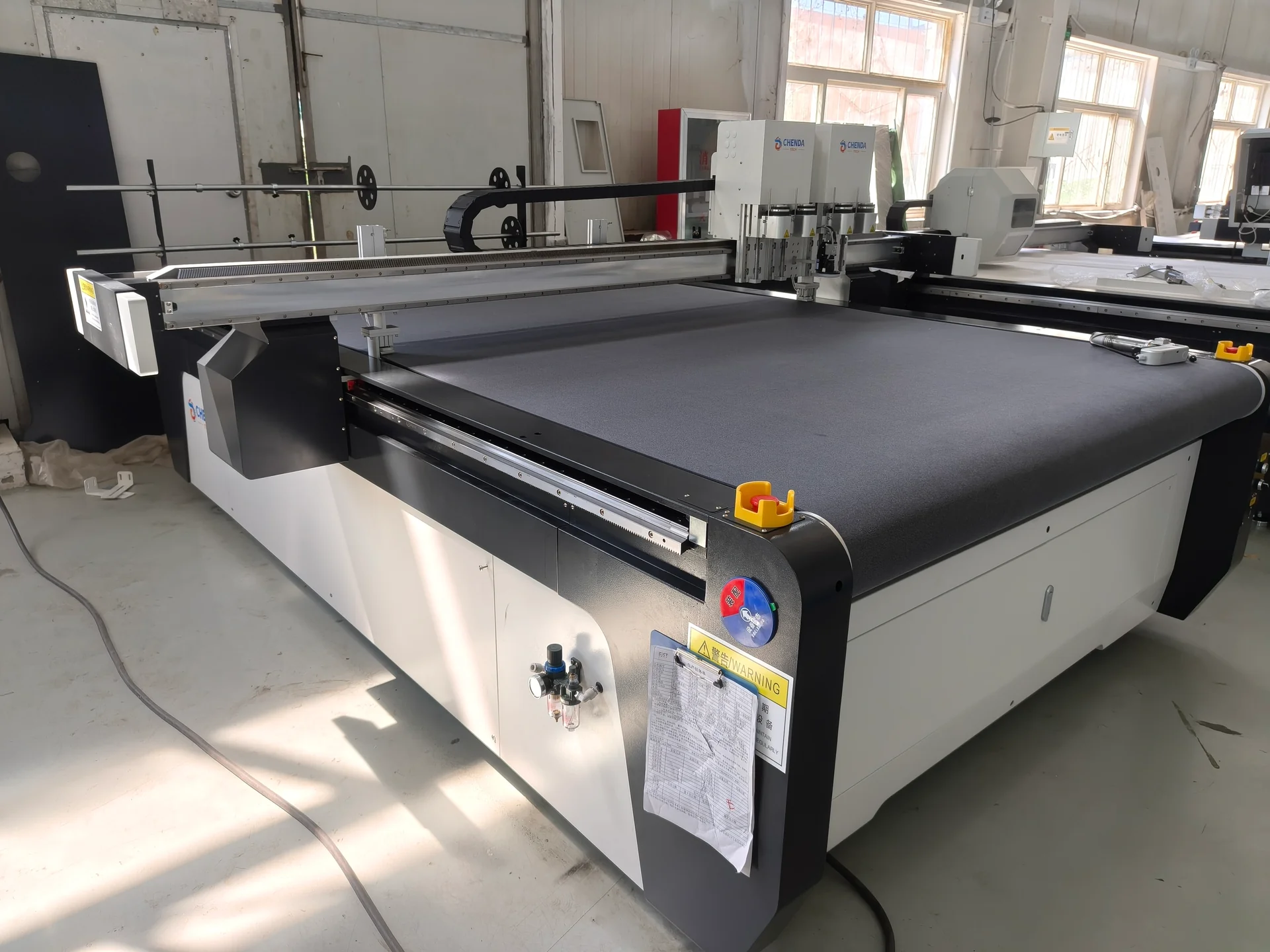
Left side of a CHENDA cutting table showing the gantry and emergency stop
Plan loading, collection and operator access
Third-party photograph of a Zünd digital cutting head above leather with colored projected nesting outlines
Match the material, tool and documented setup · Zünd (source publisher; photographer not stated)

Technical Resources

Request the tool-to-material matrix, usable table area, tested thickness conditions, file-import guide and utility requirements. For printed or roll-fed work, add the registration and feeding description. A material-specific sample record should identify the exact blade and operating arrangement.

Product FAQs

CHENDA digital knife cutting table on a white background
Third-party photograph of a Zünd digital cutting head above leather with colored projected nesting outlines
Material and tool reference · Zünd (source publisher; photographer not stated)

Can one blade cut all the materials in our workshop?

Usually a mixed workload needs more than one tool or blade. Material stiffness, density, surface layer and contour detail change the cutting action required.

CHENDA digital knife cutting table with twin tool housings and front touchscreen
Usable cutting envelope

Is cutting height the same as usable material thickness?

No. Clearance only shows whether material physically fits. Cutting force, blade reach, stability, edge quality and hold-down determine the practical thickness for a specific material.

Third-party photograph of digital cutting heads above a corrugated carton blank with cut tabs, slots and fold lines
Carton cut and crease reference · CNC Amor (source publisher; photographer not stated)

Can the cutter make fold lines as well as outlines?

Yes, where an appropriate creasing tool is included and validated for the board. Crease depth and direction should be tested by folding the actual material, not judging the line visually.

Roll support shafts and an external vacuum blower beside a digital cutting table
Material support and feed

Can a single-layer cutter be used for multiple layers?

Only within a confirmed material, compressed-height and retention specification. Sliding between layers or blade deflection can make the bottom pieces different from the top ones.

Request a Quote

Send material names and samples, thickness and density where relevant, sheet or roll dimensions, representative files and the required operations. Include layer count, printed registration needs, orientation rules, output target and the way parts will be collected. CHENDA can use these details to discuss the cutter, tools and sample conditions together.

Third-party photograph of digital cutting heads above a corrugated carton blank with cut tabs, slots and fold lines
Send the material together with its production pattern · CNC Amor (source publisher; photographer not stated)