CHENDA · Signs & displays

Cutting and Fabrication Equipment for Signs and Displays

Two materials. Two production routes.
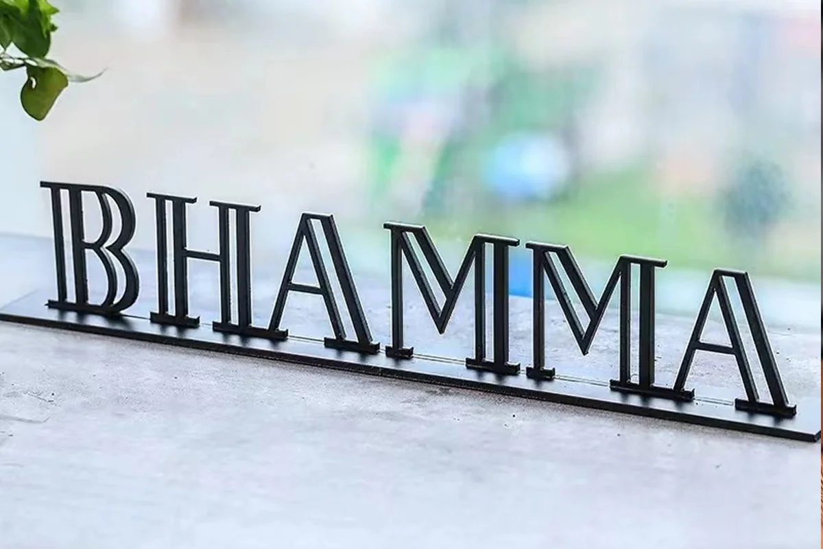
Freestanding dark metal letter sign on a base; signage application reference
Metal letter forms · application reference

Sign and display production often combines two different equipment routes. Metal letters, cabinets, brackets and frames can use laser cutting, bending, welding and finishing. Printed graphics, films, boards, foams, textiles and other compatible non-metallic materials may use digital knife cutting. These routes should be planned separately and then connected at assembly.

CHENDA offers metal fabrication equipment and a digital knife cutting direction. Material identification is the first decision. Do not assume that a metal fiber laser can process acrylic, PVC, foam, fabric or another sign substrate.

01 / Begin with the substrate

Separate the Work by Material and Operation

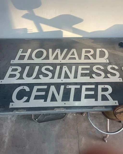
Cut metal letters and mounting holes arranged before installation; application reference
Metal lettering before installation · application reference
ROUTE 01

Metal components

Typical metal parts include letter faces or returns, sign cabinets, mounting plates, poles, brackets, frames, light boxes and display structures. Depending on the design, the route may include:

  1. Sheet metal laser cutting
  2. Deburring and edge finishing
  3. Press-brake forming
  4. Welding
  5. Cleaning, coating and assembly
  6. Laser marking for suitable identification tasks

Material grade, thickness, visible finish and coating affect each handoff. Stainless steel with a decorative face needs different scratch controls from a concealed carbon-steel bracket.
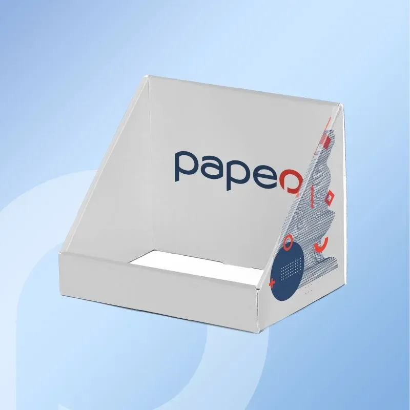
Printed folded-board counter display with raised back panel; application reference
Printed and folded board · application reference
ROUTE 02

Flexible and non-metallic graphics

Digital knife systems can be evaluated for compatible printed graphics, films, card, foam, textile and composite sheet materials. The exact tool action may include cutting, kiss cutting, creasing, perforating or another verified process. Compatibility depends on the material and selected tool.

Send the actual substrate. Trade descriptions such as “foam board” or “vinyl” can cover materials with different skins, cores, adhesives and behavior. Some materials may release hazardous dust or fumes when processed by an unsuitable technology. Review the material safety information and the machine process before testing.

02 / Form the metal structure

Metal Sign Fabrication

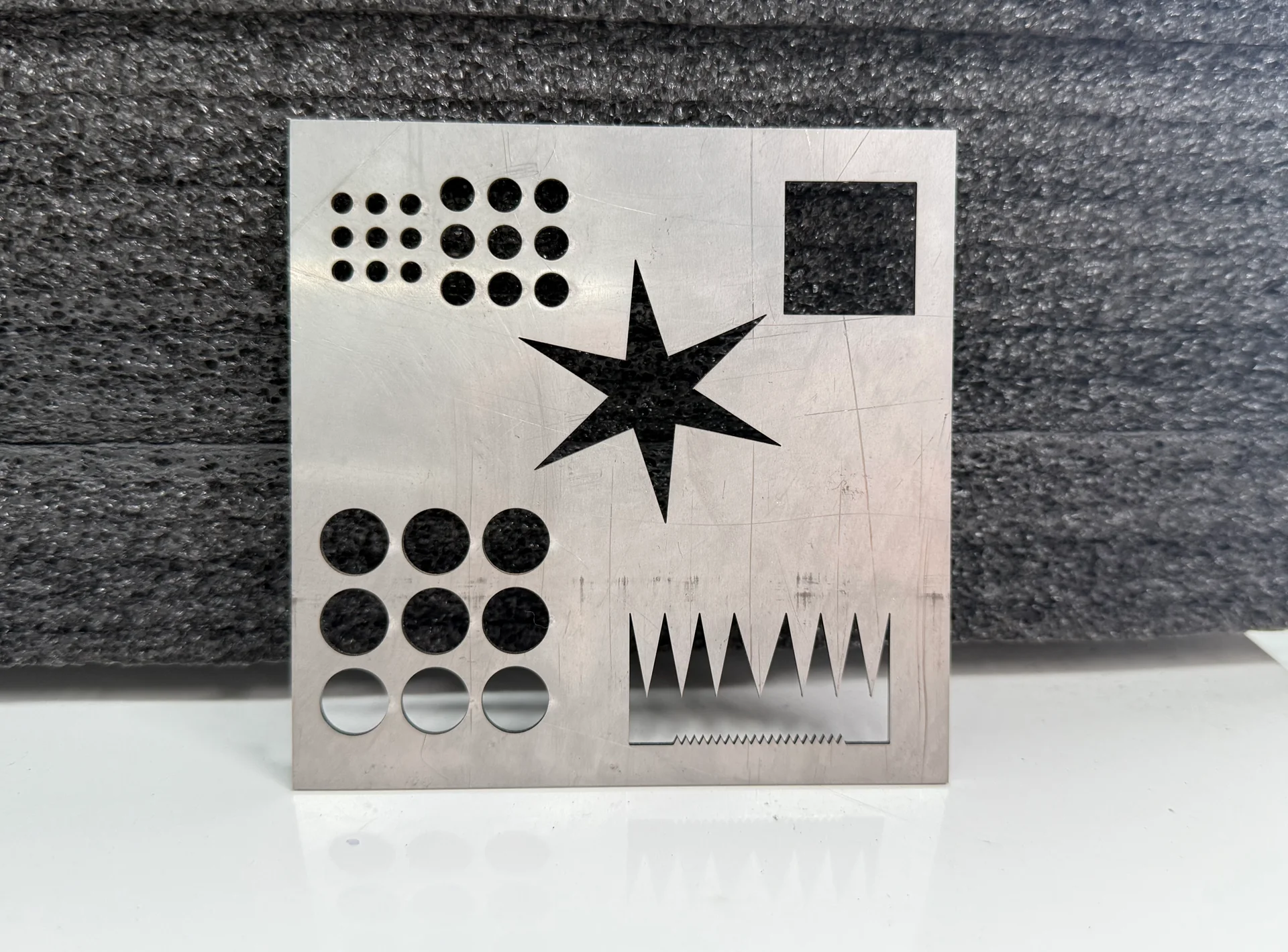
Laser-cut metal sample with holes, small corners and narrow slots
01 / DETAIL

Cutting small features

Decorative letters and logos can contain tight corners, narrow bridges, small holes and dense pierces. Define the smallest feature that must remain stable and the visible edge standard. The chosen laser source, cutting head, gas, nozzle, focus and motion must be evaluated as a system.

Nesting should preserve brushed direction, protective film and visible orientation. Marking the wrong face or rotating a directional part to save material can create unusable pieces.

Punch and V die forming a sheet; industry illustration
02 / GEOMETRY

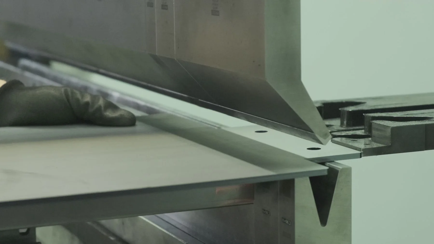
Bending letters and cabinets

Sign cabinets and returns may use long thin bends, narrow flanges, hems or boxes. Provide the finished drawing so tooling and collision can be checked. A press brake selected only from tonnage may have insufficient backgauge, daylight or tooling access for the product.

For highly varied decorative work, quick program and tooling changes matter. For repeated cabinet sizes, standardized blanks and tooling can support more automation.

Arc welding a metal assembly on a workbench; process illustration
03 / FINISH

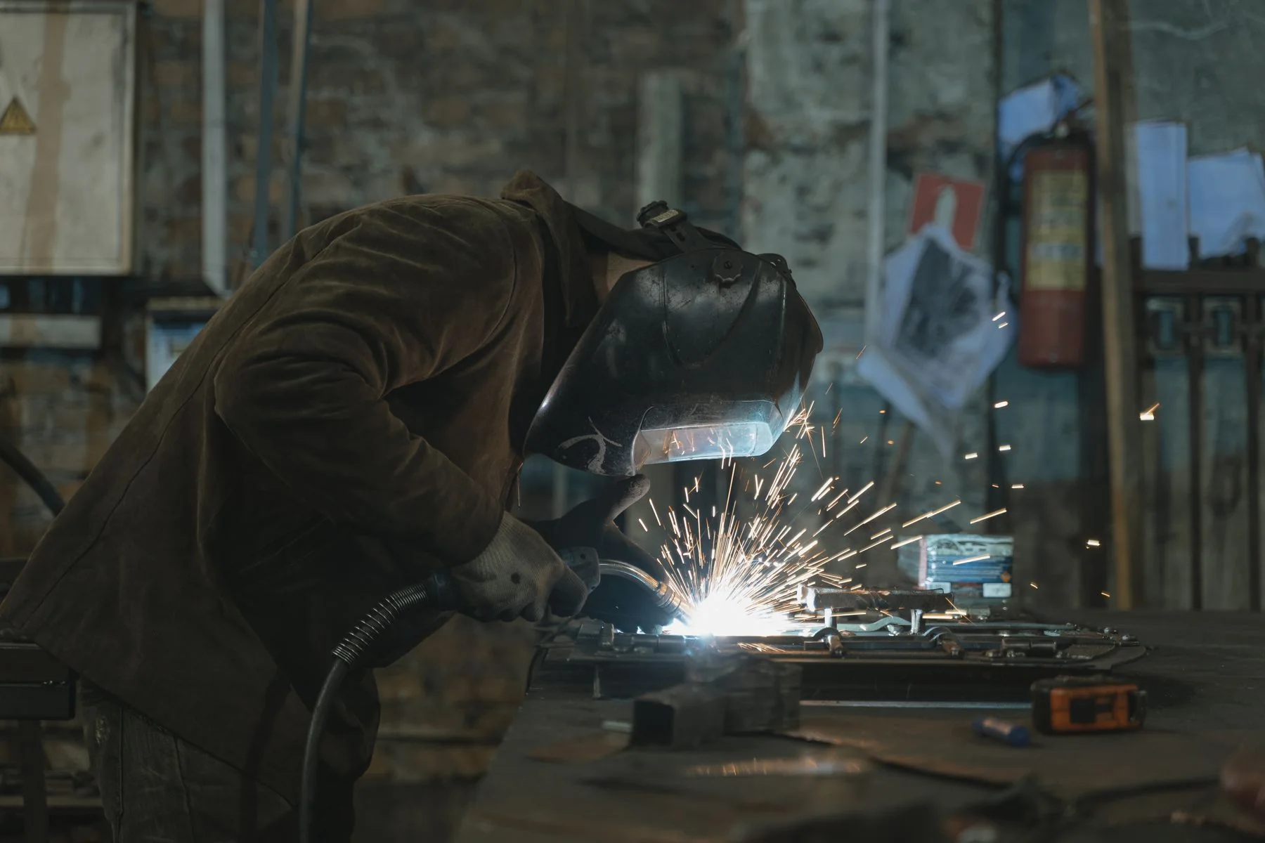
Welding visible assemblies

Visible metal signs require controlled heat and finishing. Joint design, fit-up and fixture influence distortion and the amount of grinding or polishing. Handheld laser welding may suit selected thin-metal work when gaps, material and safety are controlled. Automatic or robotic systems require more repeatable parts and fixtures.

Use a finished-corner sample for acceptance. A straight test coupon will not reveal cabinet squareness, corner draw or visible distortion.

03 / Follow the print to the cut

Digital Cutting for Printed and Display Materials

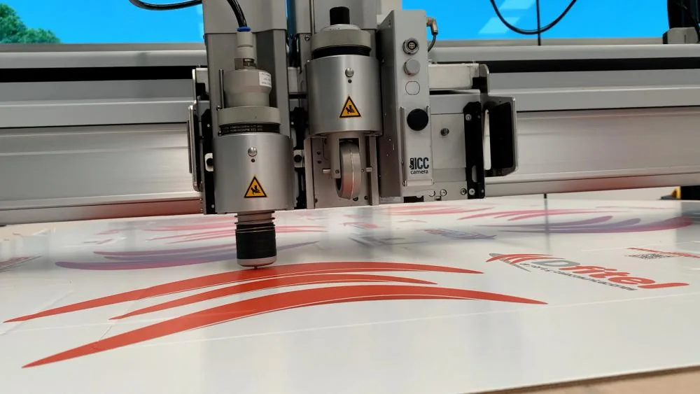
Digital cutting tools and registration camera over printed cardboard; industry reference
Camera and tooling over printed board · industry reference
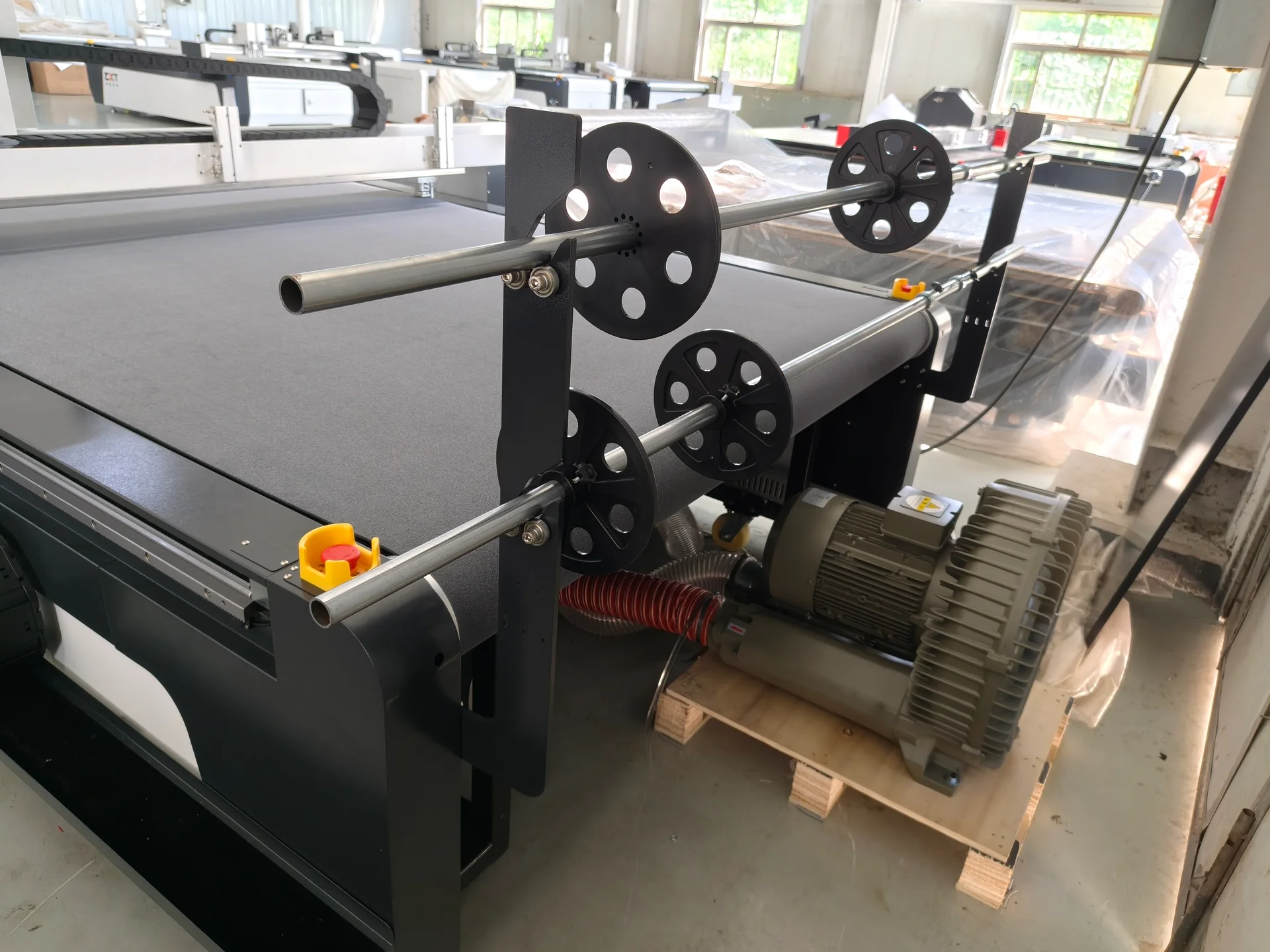
Digital cutter roll-feed hardware and vacuum blower
Roll-feed hardware and vacuum blower · equipment detail
01

File and registration

The cutting file must match the printed artwork, scale and bleed. If the system uses camera or mark recognition, test the actual registration marks, ink, laminate, lighting and distortion. Print-to-cut error can come from the printer and substrate, not only the cutter.

02

Hold-down

Vacuum hold-down depends on material porosity, table zoning, sheet flatness, size and any release liner. A porous textile and a dense board require different conditions. Small cut pieces can move after separation, so toolpath order and tabs may matter.

03

Tool selection

Drag knives, oscillating tools, driven tools, creasing wheels and other heads perform different actions. The quotation should state the tools proposed for each supplied material. Blade angle, depth, speed and replacement frequency influence edge quality and cost.

04

Part removal and assembly

Output does not end when the tool stops. Plan removal, sorting, waste stripping, labeling and protection of printed faces. Compare completed kits or assembled displays per shift rather than only machine travel speed.

04 / Compare the output

Matching the Process to the Product

Printed folded-board counter display with raised back panel; application reference
Finished display · application reference
Product Equipment route to evaluate Main quality questions
Metal letters Fiber laser, edge finishing, forming and joining Small-feature stability, visible edge, face protection and distortion
Sign cabinets and light boxes Sheet cutting, press brake and welding Squareness, door or panel fit, corner quality and coating preparation
Structural sign frames Sheet, tube or profile cutting plus welding Member length, holes, joint preparation, fixture and weld access
Printed board displays Digital knife cutting Registration, board crush, edge tearing and finished fit
Adhesive graphics and films Digital knife or kiss cutting where validated Liner control, blade depth, weedability and print registration
Fabric graphics Digital knife cutting Stretch, porosity, fraying, pattern accuracy and collection
Identification plates Sheet cutting and laser marking where compatible Mark contrast or depth, code readability and environmental durability

05 / Share each material separately

Information Required for Selection

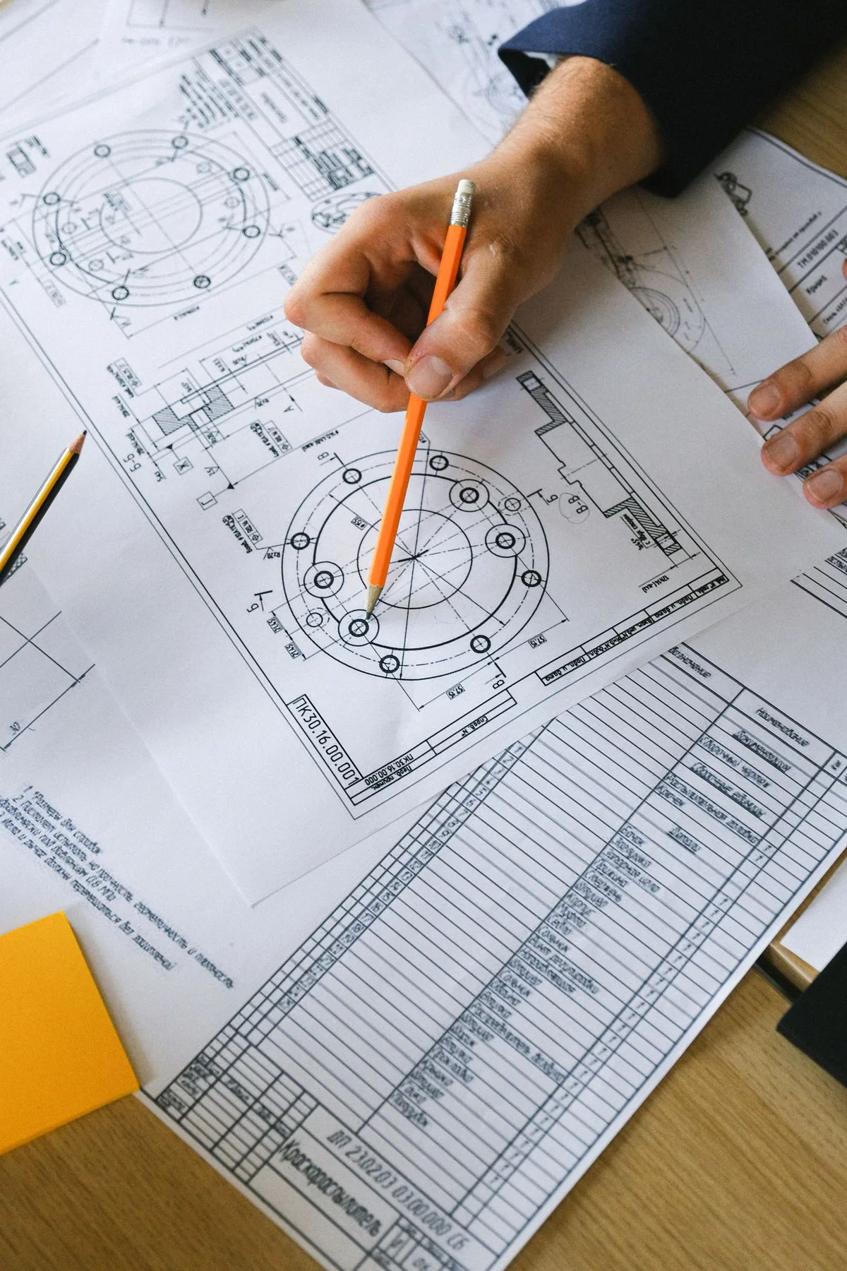
Dimensional drawing review with a pencil; industry illustration
Drawing preparation · industry illustration

Send separate lists for metal and non-metallic work:

  • Material trade name, composition and supplier data
  • Thickness, sheet or roll format and surface finish
  • Representative artwork, CAD and part drawings
  • Smallest detail and tolerance
  • Printed registration requirement
  • Bend, weld and assembly details for metal products
  • Indoor or outdoor use and expected exposure
  • Visible-face, scratch and edge standards
  • Typical batches, seasonal peaks and product mix
  • Current printing, cutting, forming and finishing equipment

For unknown materials, send samples and safety documentation before a process is proposed.

06 / Test the assembled result

Acceptance Testing

Use a sample set that represents the hardest work, not only a large simple logo. For metal, include small features, visible surfaces, bends and a joined corner. For digital cutting, include printed registration, tight curves, internal cutouts, creases or kiss cuts and the actual substrate stack.

Digital cutting tools and registration camera over printed cardboard; industry reference
Printed material and cut path · process reference

Evaluate:

  • Dimensional accuracy and scale
  • Cut-edge quality on both faces
  • Registration between artwork and cut
  • Material movement, crushed edges, tearing or fraying
  • Bend and assembly fit
  • Surface scratches, heat marks or distortion
  • Time for loading, tool change, removal and waste stripping

Assemble the sample. A cut shape that looks acceptable on the table can still fail during folding, mounting or installation.

Freestanding dark metal letter sign on a base; signage application reference
Printed folded-board counter display with raised back panel; application reference

07 / Document real work

Search and Traceability Content Worth Publishing

For each real project, record the material, process, equipment configuration, tool, finished result and limitations. Those facts create useful technical pages and future customer stories without inventing performance. High-quality photos should show the incoming material, process, edge and finished display, with customer permission.

08 / Material and process questions

Frequently Asked Questions

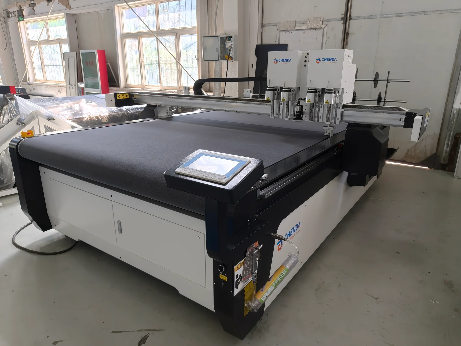
CHENDA digital knife cutting table viewed from the front right
CHENDA digital knife cutter · equipment reference

Can one laser cut both metal and acrylic signs?

Do not assume so. Fiber lasers in the CHENDA metal-cutting range are intended for compatible metals. Acrylic and other non-metallic materials use different technology. Send each substrate for process review.

When do we need a digital knife cutter instead of a laser?

Evaluate a knife system for suitable materials where mechanical cutting, creasing, kiss cutting or low-heat processing is required. The decision depends on composition, thickness, edge, output and tool availability.

Can a camera guarantee print-to-cut accuracy?

No. A vision system can locate marks or contours, but print scale, substrate stretch, lamination, lighting, file preparation and calibration still affect the finished result.

How should outdoor durability be tested?

Cutting equipment does not establish weather resistance. Use the material supplier’s data and test the finished mark, coating, adhesive and assembly under the required exposure conditions.

Laser-cut metal sample with holes, small corners and narrow slots
Metal cut geometry
Printed folded-board counter display with raised back panel; application reference
Printed board assembly