CHENDA / Equipment

CHENDA Industrial Equipment

Choose equipment around the workpiece, the process and the next production step. Jinan Chenda Tech Co., Ltd., based in Jinan, Shandong, China, brings together eight equipment families: laser cutting, press brakes, welding, laser cleaning, laser marking, deburring and finishing, digital knife cutting, and compressed-air equipment.

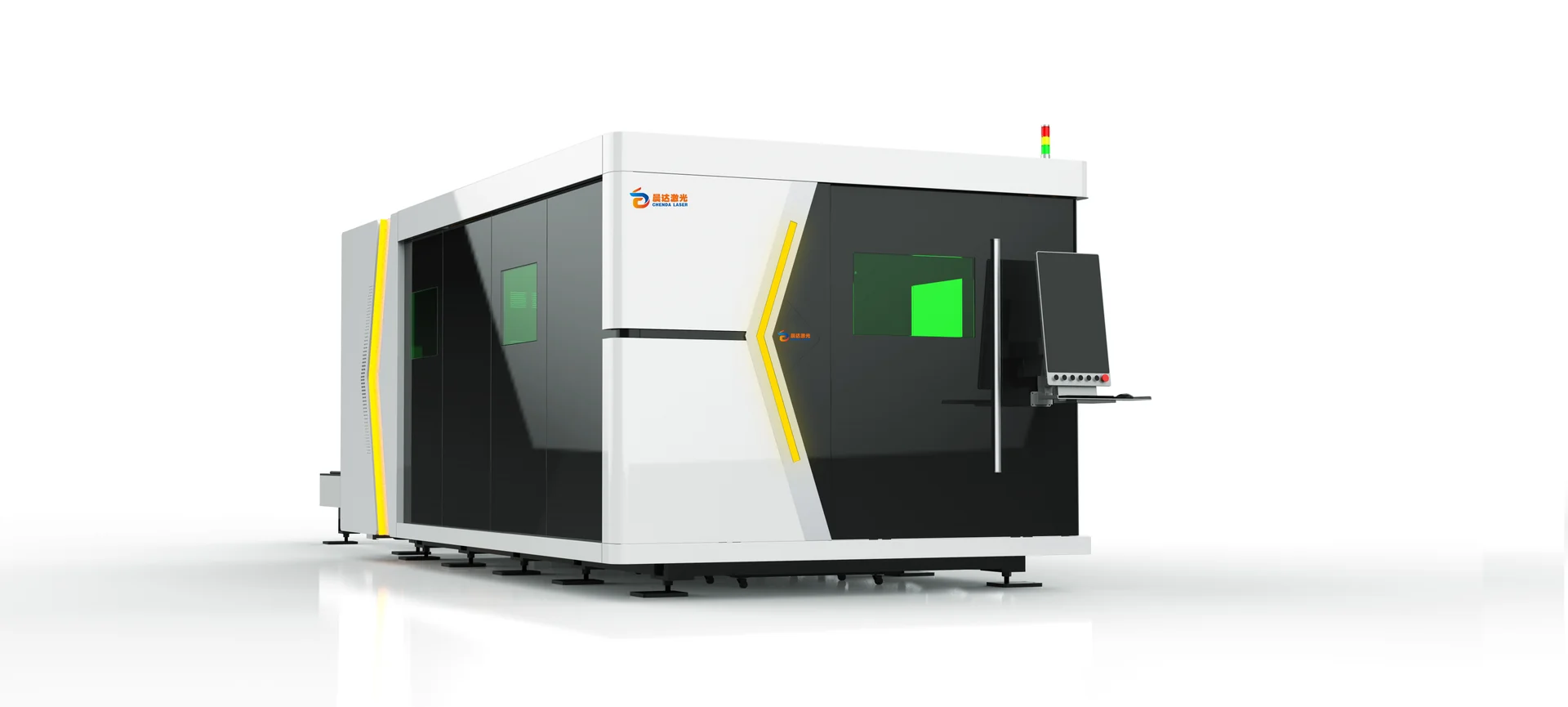
CHENDA-branded enclosed sheet laser cutter with viewing windows and operator console

Start with the material and the operation you need to improve. A flat metal blank, a welded frame, an upholstery panel and a compressed-air supply call for different selection methods. The pages below explain those differences, compare equipment directions and show what information supports a useful technical proposal.

The benefit of considering connected equipment is visible in the finished part. A clean laser-cut blank makes sense only if its edges can be handled, its flanges can be formed and its joints can be assembled. An accurate pattern matters only if the flexible material remains stable during cutting and fits when assembled. CHENDA’s product structure follows those relationships so that an equipment decision can be made in the context of production.

Find Equipment by Manufacturing Task

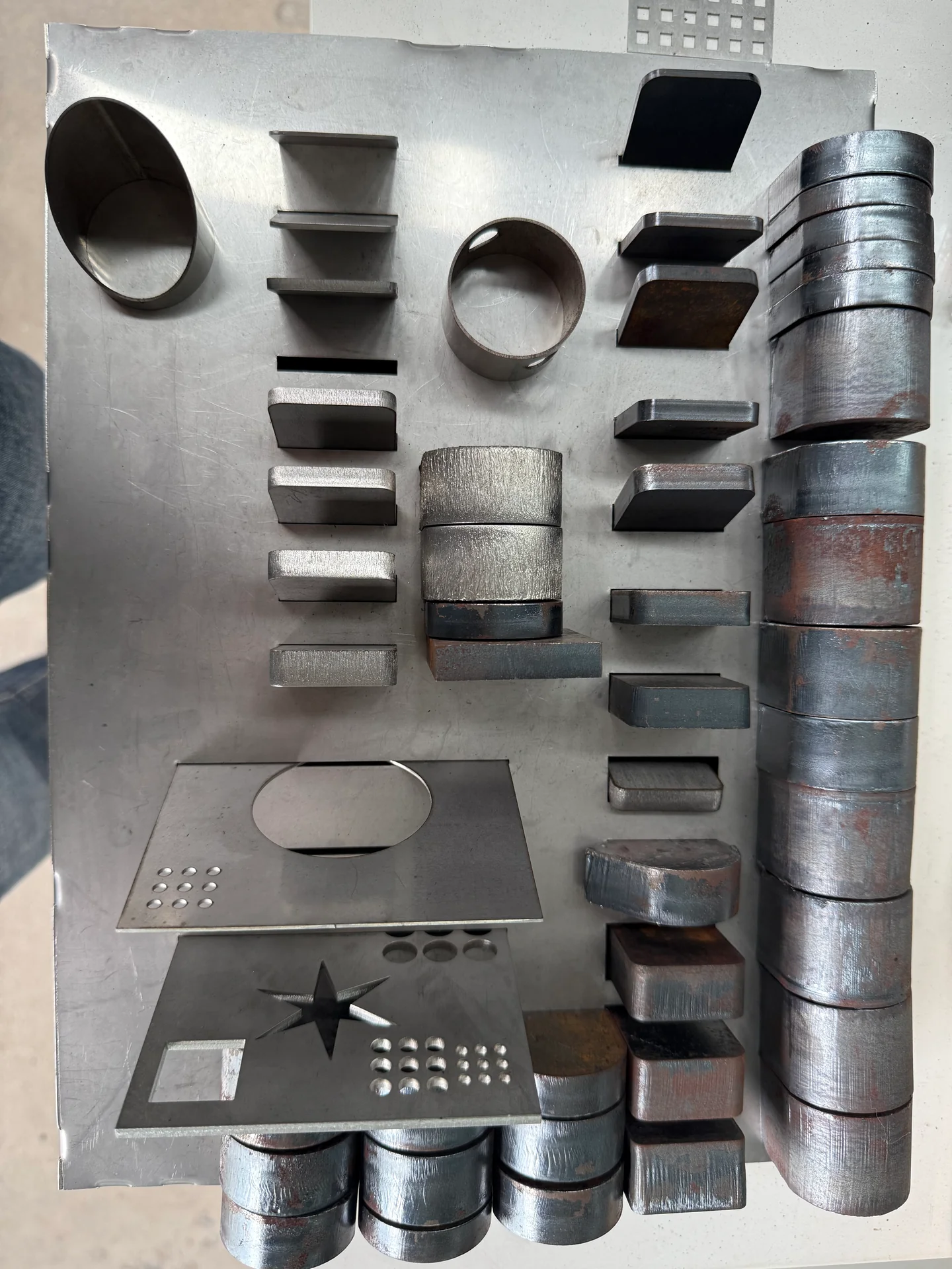
Assorted metal plate and tube samples displaying cut edges and openings
Cut parts and profiles
What you need to do Equipment family First selection questions
Cut metal sheet, tube or structural sections Laser cutting machines Material form, thickness, stock size, edge requirement and handling
Form flat blanks into finished shapes Press brakes Bend force, length, tooling, clearances and sequence
Join sheet, tube or fabricated assemblies Welding machines and systems Joint, fit-up, process, seam access and production repeatability
Remove selected surface layers Laser cleaning machines Contaminant, substrate, treatment area and acceptable surface change
Apply identification, codes or graphics Laser marking machines Material finish, mark size, contrast or depth and data handling
Remove burr, round edges or finish faces Deburring and finishing machines Incoming defect, part retention, abrasive sequence and outgoing finish
Cut suitable flexible sheet or roll materials Digital knife cutting machines Material, tool, thickness, hold-down, feeding and pattern rules
Supply clean, dry air at the required load Air compressors Flow at pressure, duty cycle, air quality and distribution
01 / Cut

Laser Cutting Machines

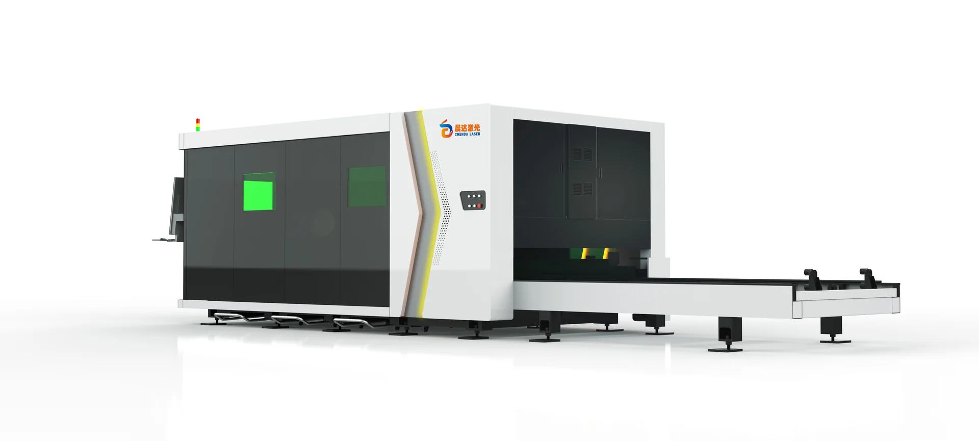
Rear view of a CHENDA-branded enclosed laser cutter showing its external exchange-table frame

The form of the raw material is the first decision. Flat sheet needs a supported cutting area and a practical loading route. Tube needs compatible chucks, stock support and a way to manage finished pieces and remaining tail material. Structural sections add flange and web access, heavy handling and joint-preparation requirements.

Sheet equipment can then be compared by table arrangement, enclosure, format and automation. A sheet-and-tube combination may suit a mixed workload, while dedicated equipment can be more appropriate when both processes need capacity at the same time.

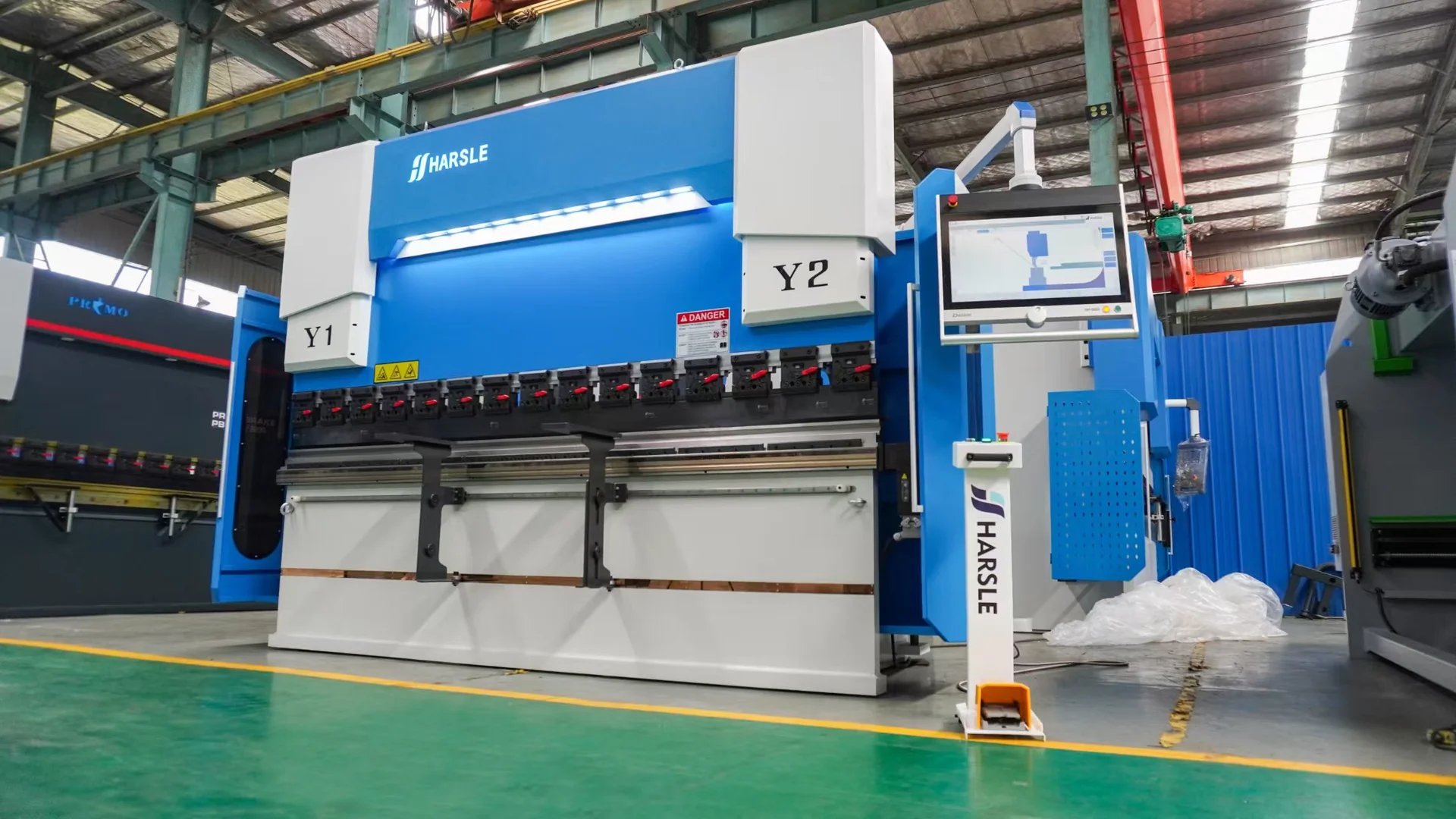
Blue and white HARSLE CNC press brake with a side-mounted controller in a workshop.
Press brake workshop · equipment reference
02 / Form

Press Brakes

Choose the forming system from the finished part, not tonnage alone. Bend length, material strength, die opening and forming method determine the force requirement. Tool shape, open height, stroke, throat and gauge access determine whether the bend sequence can actually be completed.

Torsion-bar, electro-hydraulic CNC and electric machines offer different motion and control approaches. Compare them through setup needs, repeat work, difficult flange geometry, material handling and the complete part cycle.

03 / Join

Welding Machines and Systems

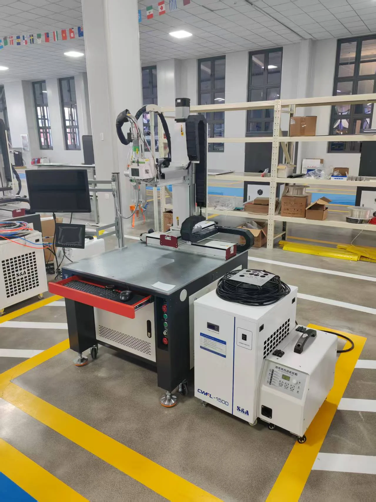
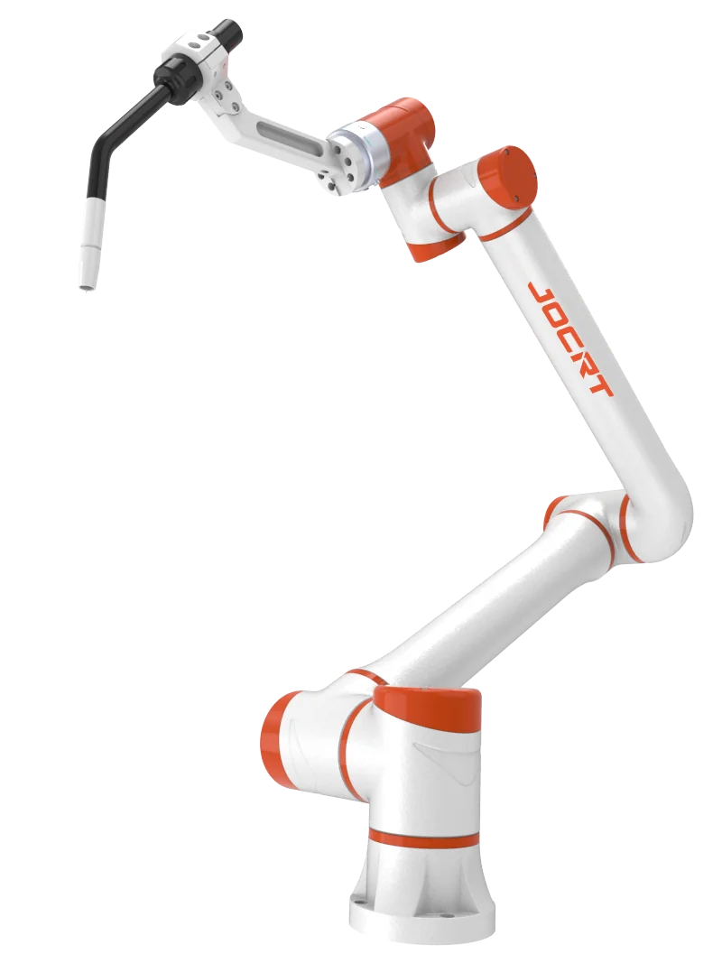
Select the joining process and the movement system together. Handheld laser welding provides operator-guided access. A programmed platform serves repeatable seams in a defined working envelope. A robot adds controlled tool orientation around more complex assemblies.

Laser and MIG/MAG welding remain separate processes. Joint preparation, filler delivery, shielding gas, heat input and inspection determine which route fits the part. Automation depends on controlled fit-up and workholding; the arm does not replace a suitable welding procedure.

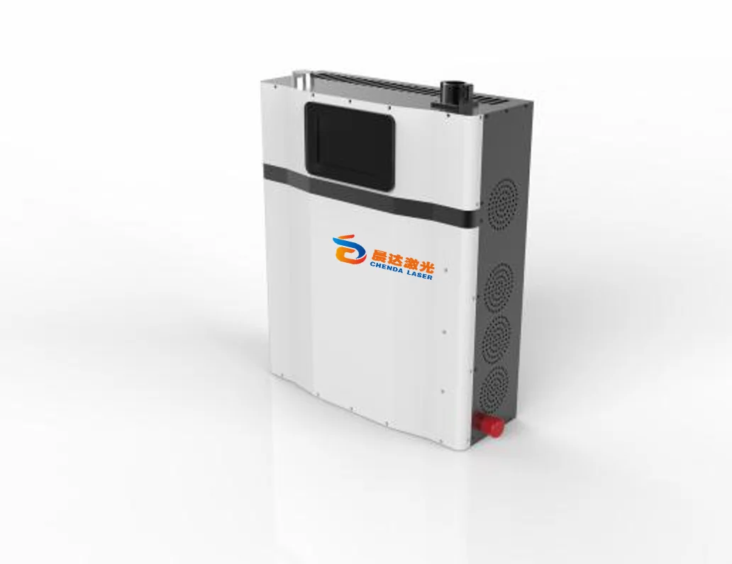
Slim upright CHENDA laser cleaning cabinet with a front display and side ventilation grilles.
04 / Clean

Laser Cleaning Machines

Define the layer to remove and the surface that must remain. Pulsed and continuous-wave laser cleaning differ in how energy is delivered, while scan pattern and working distance affect exposure across the part. Evaluate the treated surface and the next operation together, especially for coating removal, weld preparation or sensitive tooling.

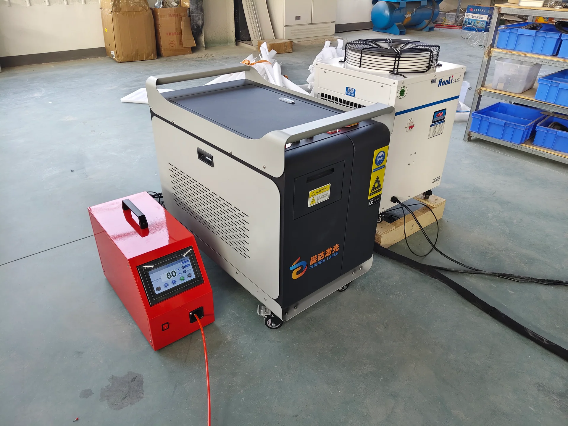
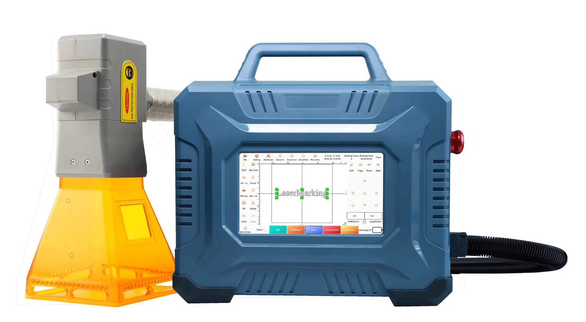
Portable laser marking unit with a touchscreen case and a connected handheld marking head.
05 / Identify

Laser Marking Machines

Start with readable information: the correct text, serial number, code or graphic in the right position. Source type, optics and material finish govern the marking effect. Fixtures, rotary motion and data integration become important when parts or information change from cycle to cycle.

06 / Finish

Deburring and Finishing Machines

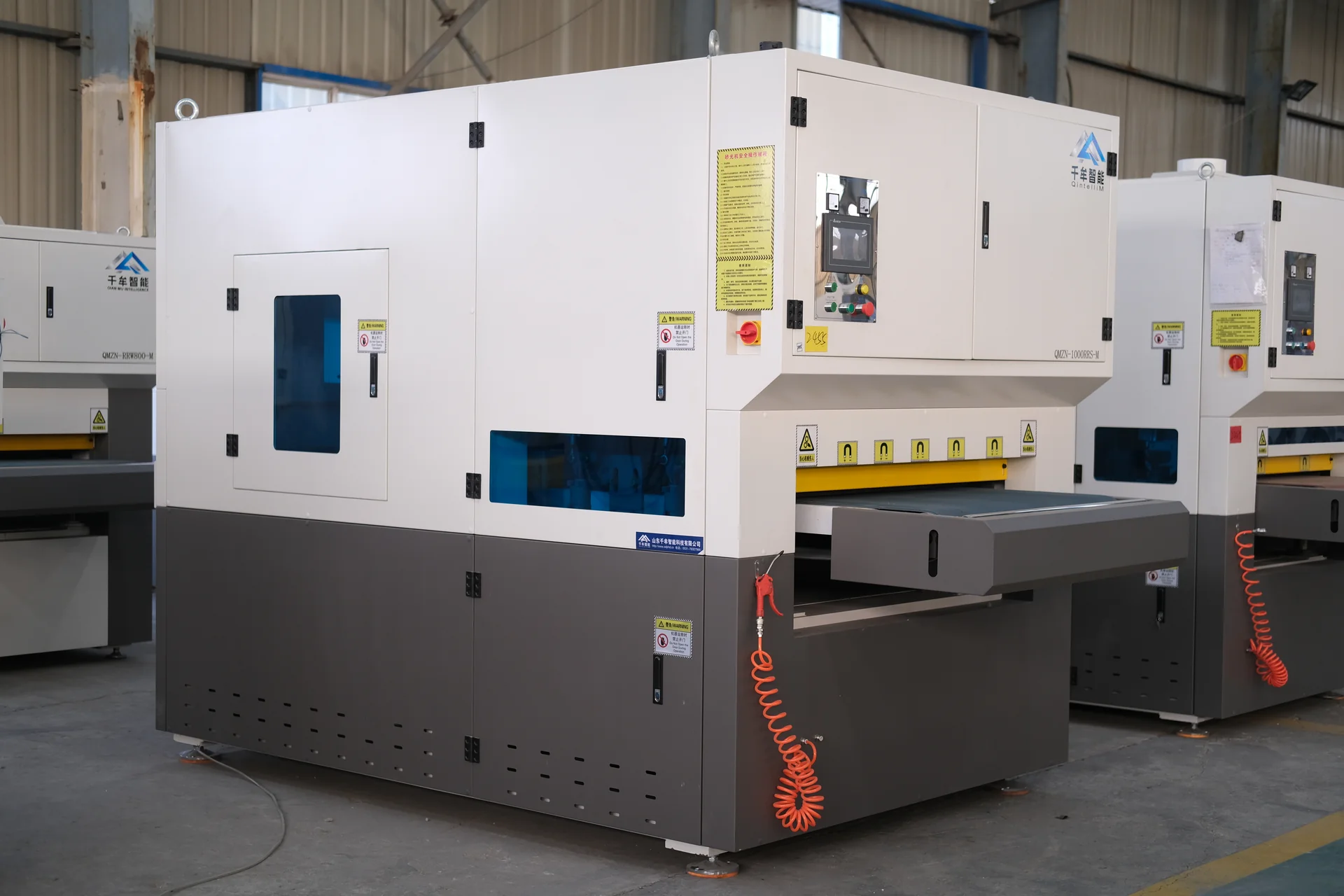
Separate raised-burr removal, edge rounding and surface finishing before selecting the abrasive stations. The machine must retain the smallest production parts as securely as it handles the largest. For visible, coated or mixed-metal work, surface protection and contamination control belong in the process choice.

Front-left view of an enclosed deburring machine with an infeed conveyor and blue side windows.
Deburring equipment reference
07 / Flexible materials

Digital Knife Cutting Machines

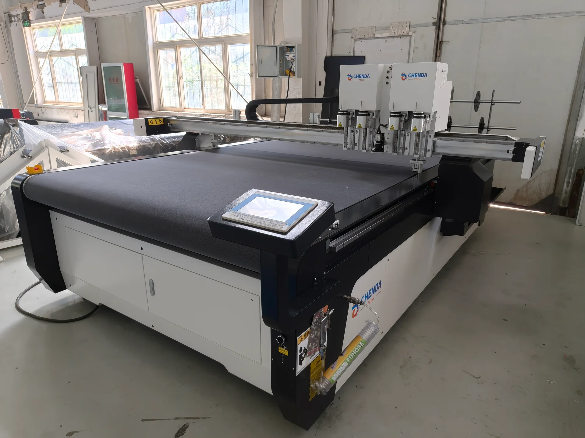
CHENDA digital knife cutting table with twin tool housings and front touchscreen

Match the tool to the material and the file to the finished component. Packaging may need both cut and crease operations; textiles need orientation and stretch control; foam requires attention to compression and edge quality. A material test should include folding, assembly or relaxed dimensions where those determine success.

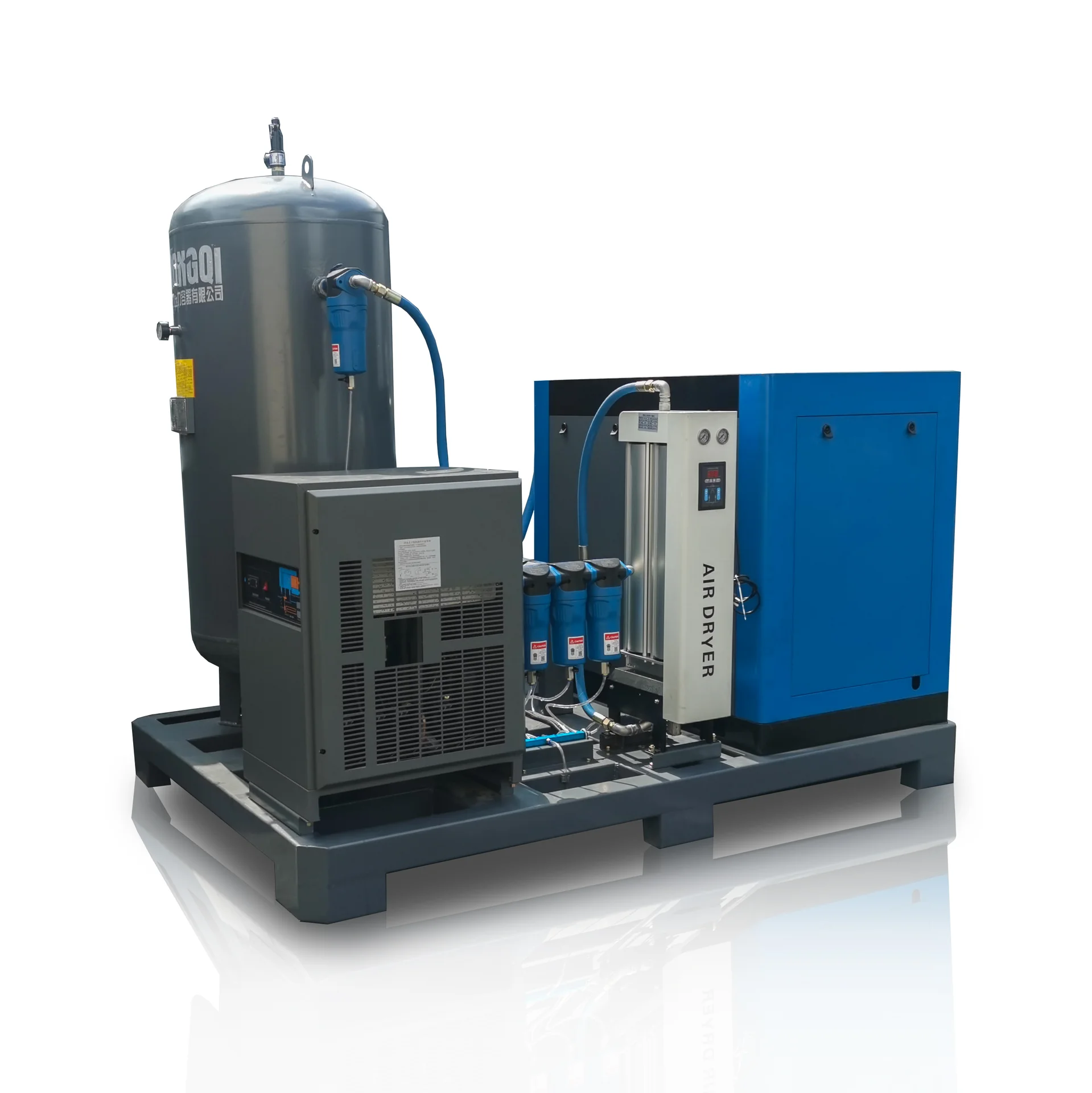
Skid-mounted air system showing a dryer and filter bank
Compressed-air system reference
08 / Supply

Air Compressors

Size the compressed-air system for delivery at the required pressure and quality. Include demand peaks, drying, filtration, storage and distribution losses. The air supply for a pneumatic actuator and the supply for an approved air-cutting process may have different requirements even when both serve the same workshop.

Connect Equipment into a Production Route

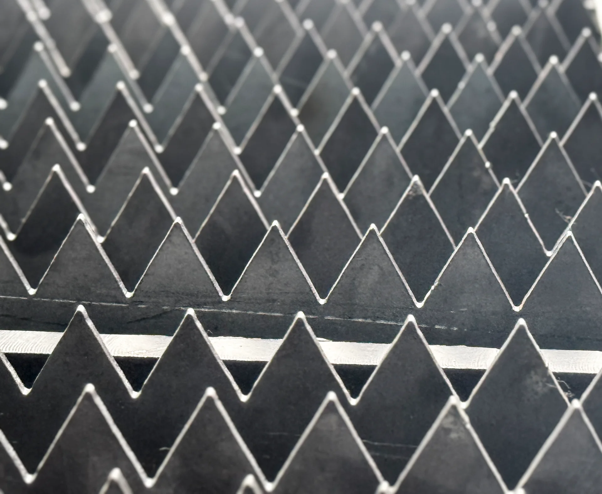
Close-up of interlocking serrated support slats on a laser cutting table
Cutting-table support detail
Production direction Typical equipment relationship Handoff that deserves attention
Sheet-metal cabinets and enclosures Sheet cutting → edge finishing → bending → welding → marking Blank accuracy, bend sequence, seam fit and visible finish
Tube frames and fabricated structures Tube or profile cutting → fit-up → welding → surface preparation Stock variation, joint access, fixtures and cooled dimensions
Packaging samples and changing short runs Digital knife cutting and creasing → folding and assembly File revision, board direction, slots and fold behavior
Upholstery and flexible components Pattern preparation → knife cutting → sorting and sewing or assembly Orientation, material movement, matched pieces and identification

These are process-planning examples. The required machines and their order depend on the actual part, incoming material and quality target. Some operations may already be covered by existing equipment.

Three Decisions That Change the Equipment Configuration

Technical drawings with a calculator and drafting compass
Drawing review · visual reference
Assorted metal plate and tube samples displaying cut edges and openings

A cabinet needs accurate handoffs between cutting, bending and welding

For an enclosure with return flanges, consider the flat pattern and formed geometry together. Holes near a bend can affect positioning or deformation. A short return can restrict punch access, while a visible welded corner makes fit-up and distortion important. Increasing laser power does not resolve those later constraints. The useful equipment combination produces a blank, bend sequence and joint that work together.

The sheet metal laser cutting page explains bed, optics, gas and handling choices. The press brake pages connect force and tooling to the formed part. The welding comparison then separates handheld, platform and robotic approaches around the actual seam.
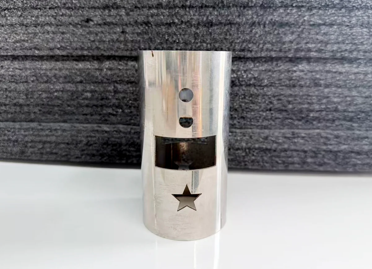
Round metal tube sample with circular holes, a rectangular window and a star-shaped opening

A tube frame needs control of stock, joint geometry and fixture location

Tube shape and straightness affect how stock is clamped and supported. A cutout close to a corner can create a different cutting condition from one on a flat wall. After cutting, the joint must still locate consistently in a fixture. The final selection therefore connects chuck range, support, remaining tail material, cut geometry and the welding route.

A robot can repeat a path only within the variation the process can tolerate. Fixtures, part datums and joint preparation deserve as much attention as nominal arm reach. For structural members, the beam’s web, flange and root geometry add a further level of cutting and connection detail.

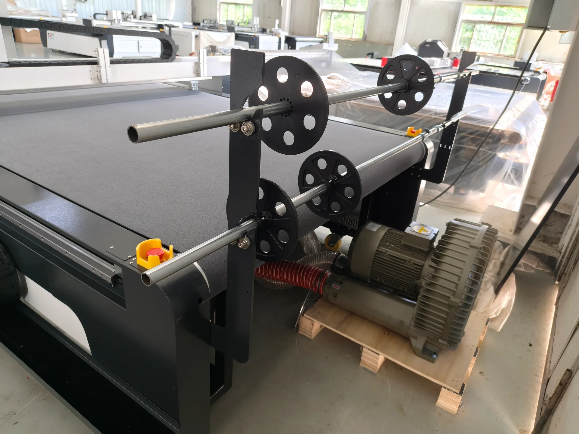
Roll support shafts and an external vacuum blower beside a digital cutting table

Flexible-material production needs a controlled material, not just a digital file

In packaging and upholstery, digital accuracy can be lost if the material stretches, moves or compresses under the tool. A carton must fold correctly after cutting; a fabric panel must retain its intended dimensions after it relaxes. Tool geometry, vacuum, feeding and orientation rules are the main selection questions. A larger table helps only when those conditions are controlled and the loading and collection route can use its area.

A Clear Basis for Working with CHENDA

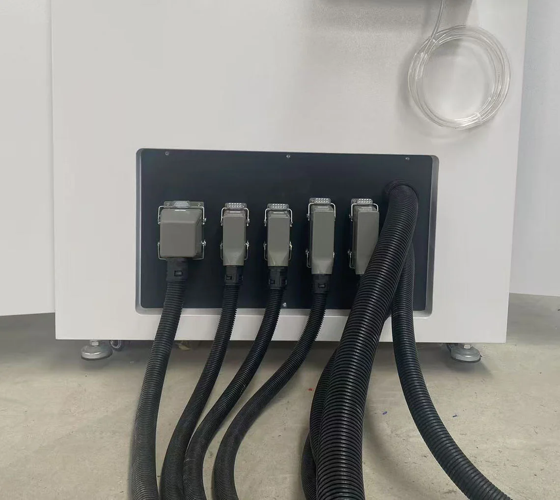
External electrical cabinet connectors with protective cable conduits
Equipment interface detail

CHENDA’s equipment pages identify catalog-listed models where a model table is available and separate them from application-dependent configurations. A listed power or working area is a useful first filter. The material, tooling, process conditions and complete supply scope explain whether that configuration fits the job.

The next level of confidence comes from connecting a proposed machine to recognizable evidence. On a laser cutter, that may be the installed source and head, a cutting file, material grade and measured sample. On a press brake, it is the tool combination and completed bend sequence. On a welding system, it is the fixture, joint conditions, procedure and inspected weld. Each family needs its own evidence; a generic demonstration cannot substitute for all of them.

The same principle carries into delivery and support. Equipment and component identities, included accessories, operating documents and agreed service responsibilities give the buyer a usable reference after shipment. The scope can include different inspection or commissioning arrangements, which should be recorded for the specific project.

Product Selection FAQs

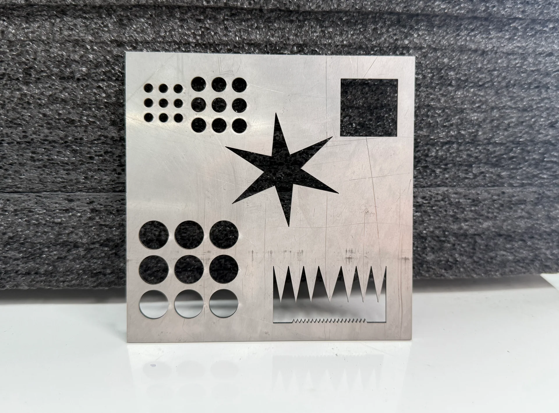
Metal cutting sample with round holes, a square opening, a star and narrow triangular cutouts
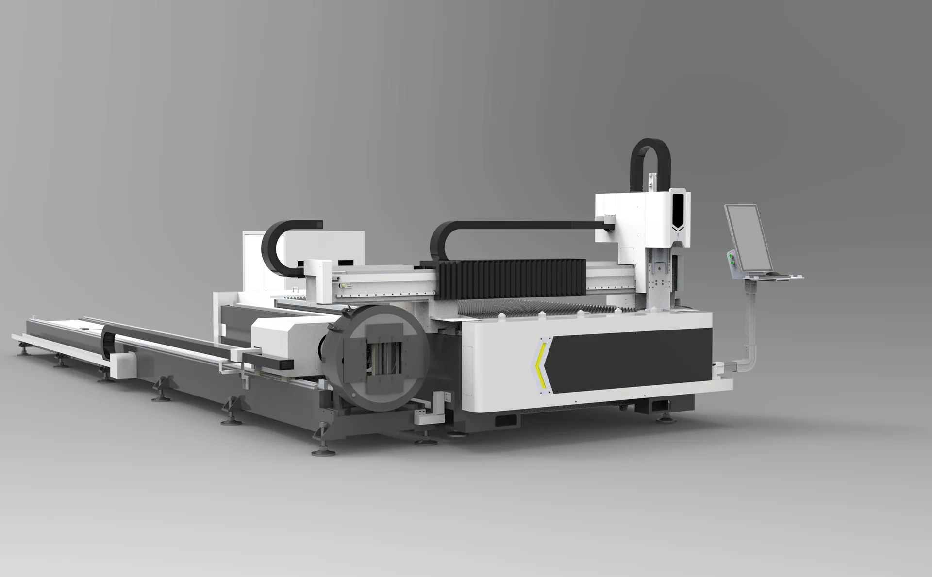
Combined sheet and tube laser cutter with an open sheet table and adjacent rotary chuck line

Where should we start if several machines need replacing?

Identify the constraint in the complete production route. The slowest or least reliable handoff may be part handling, fit-up or sorting rather than the machine with the lowest advertised processing speed. Send representative parts and the current workflow to narrow the first equipment decision.

Round metal tube sample with circular holes, a rectangular window and a star-shaped opening

Can we compare several configurations for the same part?

Yes. Use the same drawing, material and outgoing requirement, then compare process capability, total cycle, required operators, utilities and included scope. Catalog figures are useful starting points; a configuration-specific proposal makes the comparison actionable.

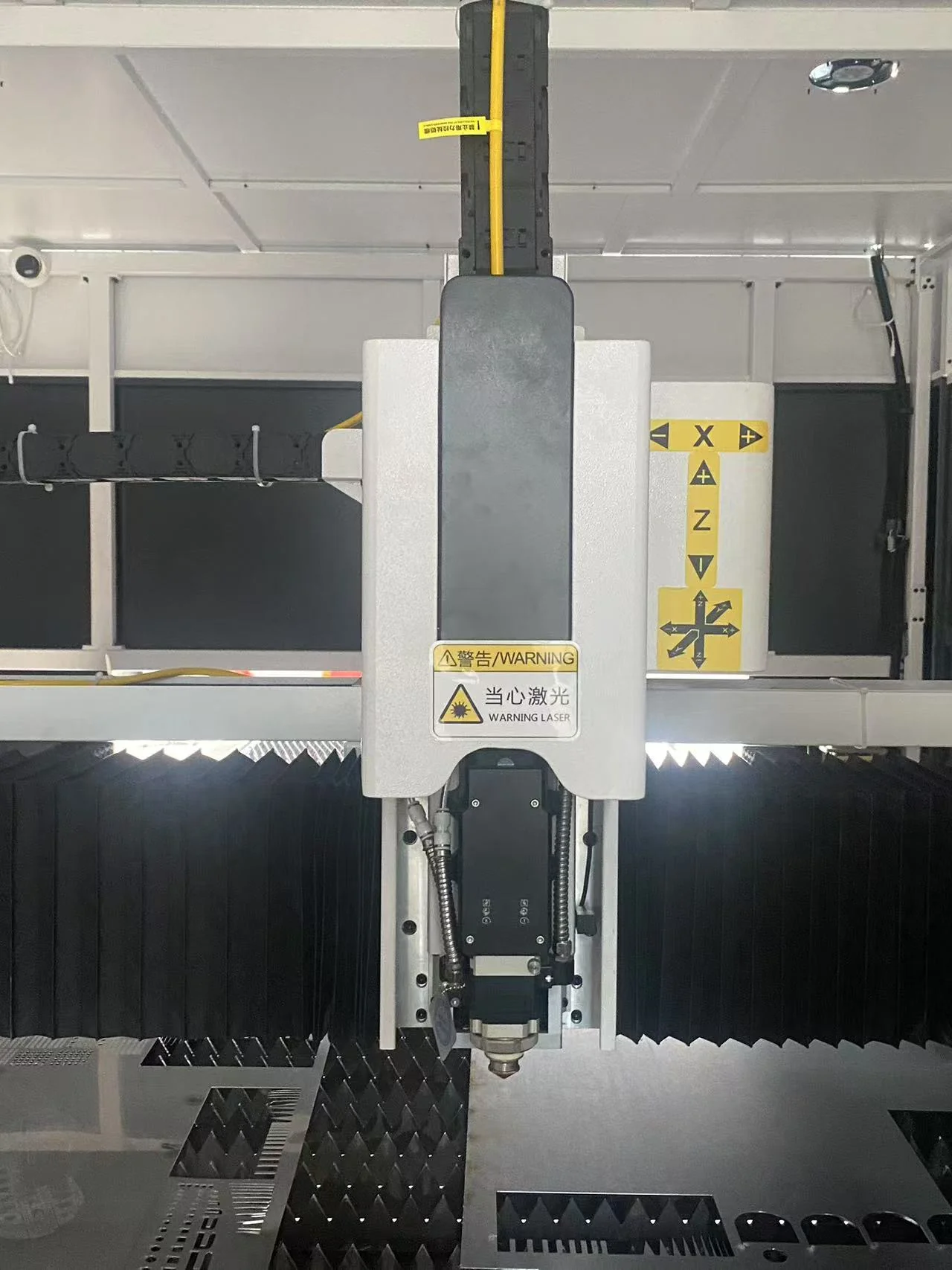
Installed laser cutting head above a metal sheet and slatted cutting table

What if our material or application is unusual?

Provide the material specification, a sample and the required result. A sample plan can address the uncertain operation before the wider equipment package is finalized. The relevant product page explains which details matter for each process.

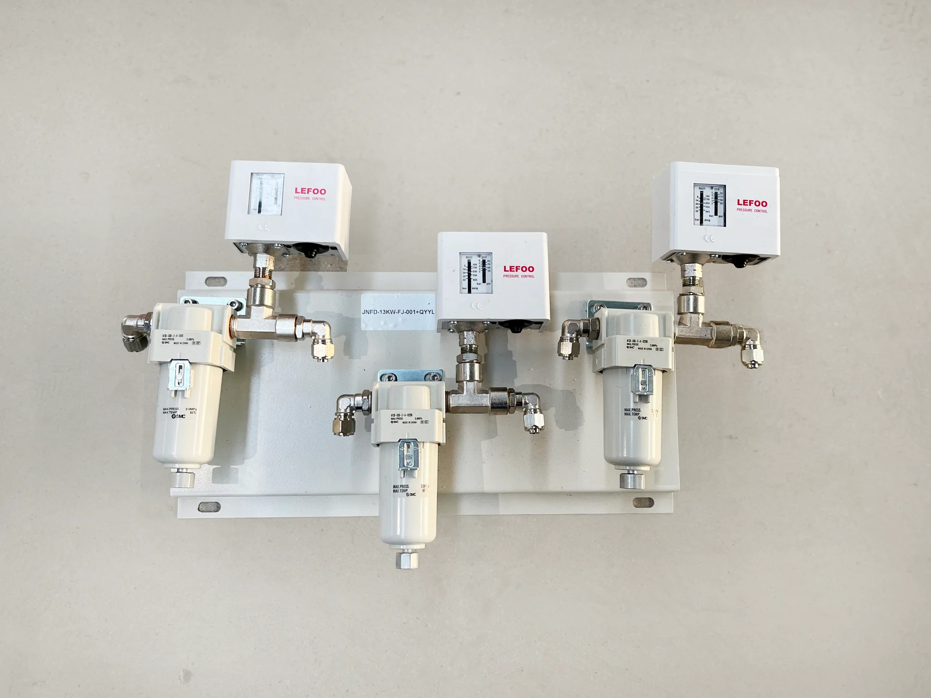
Gas-line assembly with LEFOO pressure switches and SMC filter units

Can CHENDA discuss supporting equipment as well as the main machine?

Yes. Identify needs such as extraction, air treatment, cooling, fixtures, loading and unloading when describing the application. Inclusion, interfaces and responsibilities should be clear in the equipment proposal.

Turn Your Part into an Equipment Proposal

Send drawings or patterns, material grades, normal and maximum sizes, production quantities and the result you need to achieve. Add the current bottleneck, available space, utilities and destination. Where several processes are involved, include a simple description of how the part moves through the workshop.

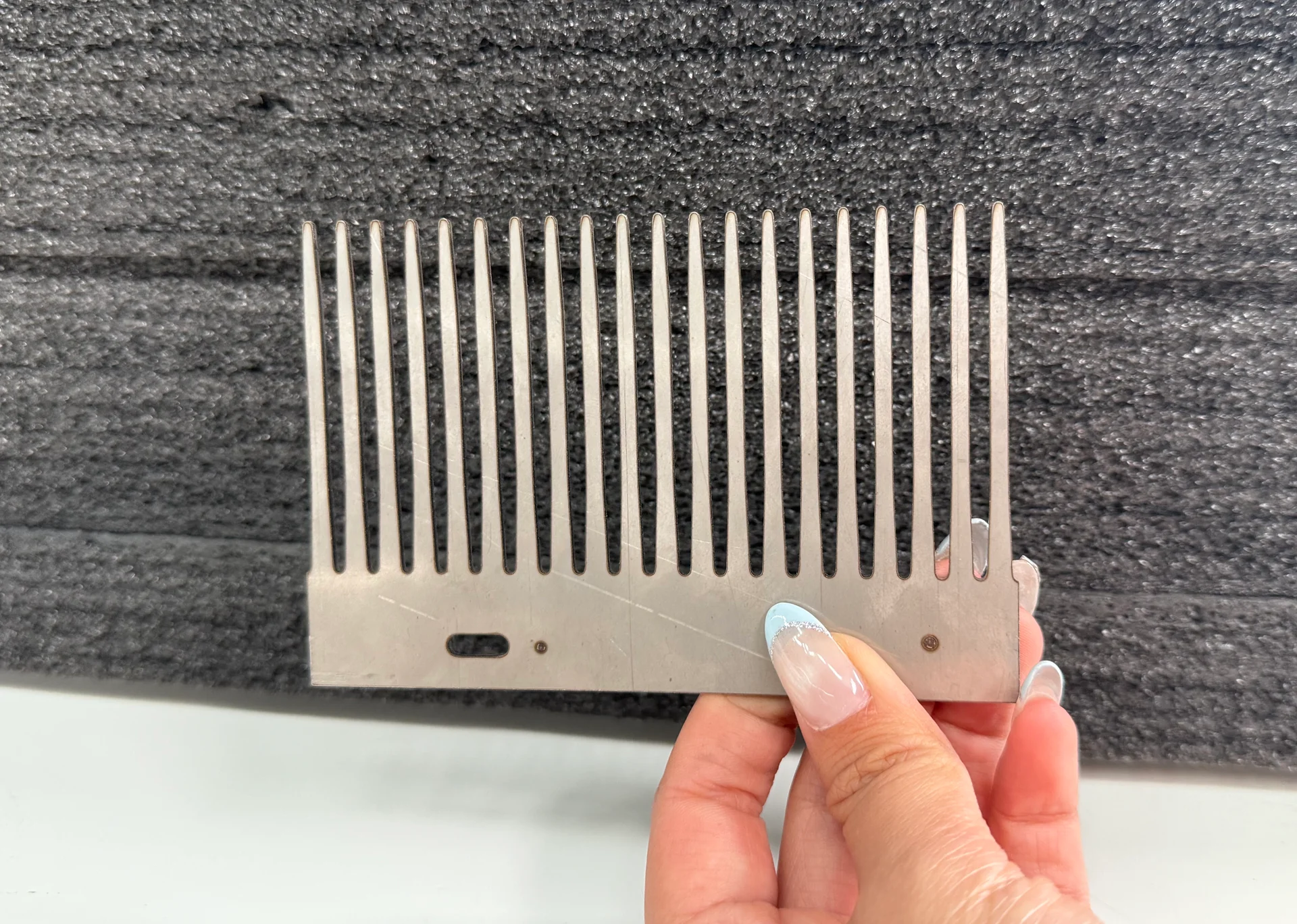
Hand-held metal cutting sample with a row of long narrow slots
Start with the details of your part